BE1-49 Functional Description
3-1
POWER
SUPPLY
SENSOR
POWER
SUPPLY
CONSTANT
CURRENT
SOURCE
UPPER
TEMPERATURE
COMPARATOR
LOWER
TEMPERATURE
COMPARATOR
AMPLIFIER
OUTPUT
DRIVER
(LOW)
OUTPUT
DRIVER
(HIGH)
POWER
SUPPLY
STATUS
UPPER
TEMP.
OUTPUT
LOWER
TEMP.
OUTPUT
REFERENCE
VOLTAGE
SUPPLY
R
T
D
1
POWER
INPUT
OPERATING
VOLTAGE
UPPER
TEMP.
LIMIT
LOWER
TEMP.
LIMIT
SET OPTIONAL
LATCH
RESET
THE BE1-49 TEMPERATURE RELAY REQUIRES FOUR WIRES FOR THE
RTD. ONE PAIR PROVIDES CONSTANT CURRENT AND THE SECOND
PAIR MONITORS THE RTD VOLTAGE DROP. THIS CONFIGURATION
ELIMINATES MATCHING THE RESISTANCE OF THE LEADS. NO
BALANCING OF LEAD RESISTANCE OR REGARD FOR WIRE LENGTH IS
NECESSARY AS LONG AS THE TOTAL RESISTANCE OF THE WIRING IN
THE RTD CIRCUIT IS LESS THAN 20 OHMS.
D2817-08
07-09-98
3
4
9
7
6
11
12
AUXILIARY
OUTPUTS
1
17
18
19
10
TGT
2
10
1
8
Paddle Operated Shorting Bars
SECTION 3 • FUNCTIONAL DESCRIPTION
INTRODUCTION
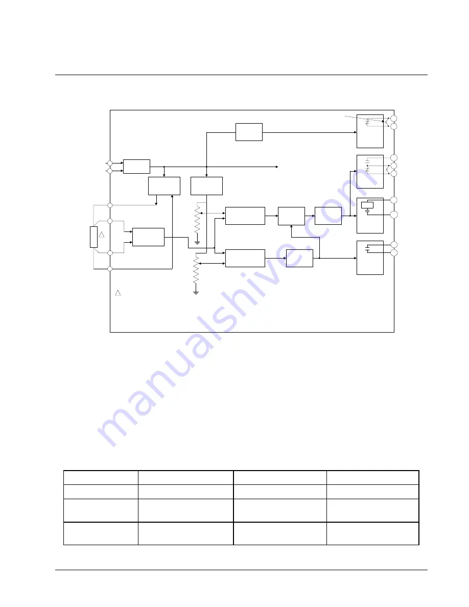
The following paragraphs and Figure 3-1 provide a functional description of the BE1-49 relay.
Figure 3-1. Functional Block Diagram
Power Supply
Basler Electric enhanced the power supply design for unit case relays. The new design created three, wide- range
power supplies that replace the six previous power supplies. Style number identifiers for these power supplies
have not been changed so that customers may order the same style numbers that they ordered previously. The
first newly designed power supplies were installed in unit case relays with EIA date codes 9638 (third week of
September 1996). The new power supply design is indicated by a circuit board part number of 9 2757 XX XXX.
The older power supply design is indicated by a circuit board part number of 9 1431 XX XXX. A benefit of the new
design increases the power supply operating ranges such that the 48/125 volt selector is no longer necessary.
Specific voltage ranges for the three new power supplies and a cross reference to the style number identifiers are
shown in Table 3-1.
Table 3-1. Wide Range Power Supply Voltage Ranges
Power Supply
Style Chart Identifiers
Nominal Voltage
Voltage Range
Low Range
D
24 Vdc
12
t
to 32 Vdc
Mid Range
B, C, E, W
48, 125 Vdc,
120 Vac
24 to 150 Vdc,
90 to 132 Vac
High Range
X
125, 250 Vdc,
120, 240 Vac
62 to 280 Vdc,
90 to 270 Vac
t
14 Vdc is required to start the power supply.
Summary of Contents for BE1-49
Page 2: ......
Page 6: ...This page intentionally left blank...
Page 12: ...This page intentionally left blank...
Page 18: ...This page intentionally left blank...
Page 27: ...BE1 49 Installation 4 9 Figure 4 8 S1 Case Panel Drilling Diagram Semi Flush Mounting...
Page 30: ...4 12 BE1 49 Installation Figure 4 11 DC Connection Diagram...
Page 38: ...This page intentionally left blank...
Page 40: ...This page intentionally left blank...
Page 41: ......


