9252000892 Rev A
BE1-50/51B-229 Installation
4-3
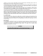
From the reset characteristic curve equation:
seconds
5
.
15
1
0
2
75
.
7
)
1
(
2
2
Re
−
=
−
×
=
−
=
Trip
Trip
set
T
T
M
RD
T
M equals zero if the current decreases to zero. A negative result indicates reset time.
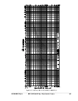
The results from the two equations give a full trip time of 0.209 seconds and a full reset time of 15.5
seconds if the current goes to zero.
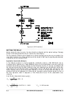
In the coordination timing diagram of Figure 4-3:
T
A
= 0.209 seconds (relay was at reset)
T
B
= value < T
A
because rewind has not gone to
zero
T
C
= value <T
A
because rewind has not gone to zero
Figure 4-3. Coordination Timing Diagram
The equation for the time to trip during rewind (before relay is reset) is:
FullRewind
RewindTime
FullTrip
T
Occurance
This
Trip
×
=
Second Operation:
seconds
0.040
T
5
.
15
3
209
.
0
B
=
×
=
B
T
Third Operation:
seconds
0.161
T
5
.
15
96
.
11
209
.
0
c
=
×
=
C
T
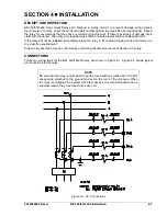
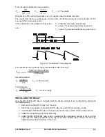
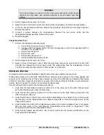
INSTALLING THE RELAY
Once the BE1-50/51B-229 relay is configured with the desired settings, it can be installed by performing
the following steps.
1. Remove the existing SFC relay from the case.
2. Attach the cover adaptor to the existing SFC relay case with the four screws provided.
3. Insert the BE1-50/51B-229 relay in the case and lock the relay in place with the cradle latches.
4. Install the connection plug from the SFC relay.
5. Install the BE1-50/51B-229 relay cover by positioning the interlocking bracket at the top of the
cover into the mating receptacle at the top of the cover adaptor plate. Secure the cover by
tightening the knob at the bottom of the cover.
Summary of Contents for BE1-50/51B-229
Page 2: ......
Page 6: ...iv BE1 50 51B 229 Introduction 9252000892 Rev A This page intentionally left blank ...
Page 8: ...vi BE1 50 51B 229 Introduction 9252000892 Rev A This page intentionally left blank ...
Page 10: ...ii BE1 50 51B 229 General Information 9252000892 Rev A This page intentionally left blank ...
Page 20: ...ii BE1 50 51B 229 Controls and Indicators 9252000892 Rev A This page intentionally left blank ...
Page 26: ...ii BE1 50 51B 229 Functional Description 9252000892 Rev A This page intentionally left blank ...
Page 30: ...ii BE1 50 51B 229 Installation 9252000892 Rev A This page intentionally left blank ...
Page 34: ...4 4 BE1 50 51B 229 Installation 9252000892 Rev A This page intentionally left blank ...
Page 36: ...ii BE1 50 51B 229 Testing 9252000892 Rev A This page intentionally left blank ...

