3-2
BE1-50 Functional Description
Response Characteristics
Input current signals are rectified and passed through a low pass filter. Filtering smooths out current spikes
and provides a degree of security against operation on short term transients.
Filtering also smooths out the harmonic component effects on current signals. Harmonic component effects
are reduced approximately by 1/
n where n is the order of the harmonic. For example, the third harmonic
effect is reduced by filtering to 1/3rd. of what it would be without filtering. With filtering, the response
characteristics are similar to those of electromechanical relays.
Pickup Settings
A front panel multiple-turn potentiometer controls the pickup setting for all phases. The potentiometer
establishes the reference voltage representative of the system current which will cause the relay to respond.
On relay styles monitoring neutral current, an independent potentiometer is provided to establish the pickup
level for neutral.
Pickup Comparators
The magnitude of each monitored current is compared with the appropriate pickup setting. When a pickup
setting is exceeded, a pulse stretcher for that phase (or neutral) is activated.
Pulse Stretchers
Because the sensed currents are full-wave rectified and minimally filtered to retain high speed operation,
the pulse output from the comparators must be extended.
Outputs
Defined by the style number, individual output relays may be provided for each monitored phase (and
neutral). One output relay may serve for all monitored phases (and neutral). In addition, one auxiliary output
relay may be provided that serves for all monitored phases (and neutral).
Targets
Magnetically latching target indicators may be provided for each monitored phase and neutral. These
targets are actuated upon an overcurrent condition and may be either internally operated or current operat-
ed. Current operated targets require a minimum of 0.2 A flowing through their corresponding output relay's
contacts. Target indicators may be reset with the manual reset lever.
Power Supply
Basler Electric enhanced the power supply design for unit case relays. This new design created three, wide
range power supplies that replace the five previous power supplies. Style number identifiers for these power
supplies have not been changed so that customers may order the same style numbers that they ordered
previously. The first newly designed power supplies were installed in unit case relays with EIA date codes
9638 (third week of September 1996). Relays with a serial number that consists of one alpha character
followed by eight numerical characters also have the new wide range power supplies. A benefit of this new
design increases the power supply operating ranges such that the 48/125 volt selector is no longer
necessary. Specific voltage ranges for the three new power supplies and a cross reference to the style
number identifiers are shown in the following table.
Summary of Contents for BE1-50
Page 1: ... 05647 6 10 07 14 056 06 0 175 18 4 744 06 4 Publication 9 1710 00 990 Revision C 11 98 ...
Page 5: ...iv BE1 50 Introduction CONTENTS Continued SECTION 7 MANUAL CHANGE INFORMATION 7 1 Changes 7 1 ...
Page 12: ...2 2 BE1 50 Human Machine Interface Figure 2 1 Location of Controls and Indicators ...
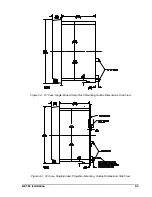
Page 20: ...BE1 50 Installation 4 5 Figure 4 7 S1 Case Single Ended Panel Drilling Diagram Rear View ...
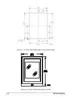
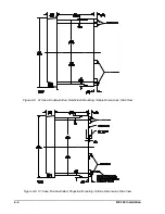
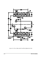
Page 21: ...4 6 BE1 50 Installation Figure 4 8 S1 Case Double Ended Panel Drilling Diagram Rear View ...
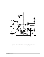
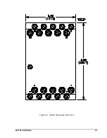
Page 22: ...BE1 50 Installation 4 7 Figure 4 9 Outline Dimensions Rear View ...


