background image

9170700990 Rev D 

BE1-60 Controls and Indicators 

2-1 

SECTION 2 

 CONTROLS AND INDICATORS 

INTRODUCTION 

All BE1-60 controls and indicators are located on the relay front panel. The controls and indicators are 
shown in Figure 2-1 and described in Table 2-1. 


Figure 2-1. BE1-60 Controls and Indicators 

Summary of Contents for BE1-60

Page 1: ...INSTRUCTION MANUAL FOR VOLTAGE BALANCE RELAY BE1 60 Publication 9170700990 Revision D 09 07...

Page 2: ......

Page 3: ...and Indicators Functional Description Installation Testing WARNING To avoid personal injury or equipment damage only qualified personnel should perform the procedures in this manual NOTE Be sure that...

Page 4: ...r operation The availability and design of all features and options are subject to modification without notice Should further information be required contact Basler Electric BASLER ELECTRIC ROUTE 143...

Page 5: ...ontact ratings in Section 1 Updated Target Indicator description in Section 3 C 06 03 Changed unit of measure for single phase sensing values from VL N and VL L to Vac Corrected terminal number error...

Page 6: ...iv BE1 60 Introduction 9170700990 Rev D This page intentionally left blank...

Page 7: ...rature 1 6 UL Recognition 1 6 GOST R 1 6 Weight 1 6 Case Size 1 6 SECTION 2 CONTROLS AND INDICATORS 2 1 INTRODUCTION 2 1 SECTION 3 FUNCTIONAL DESCRIPTION 3 1 INTRODUCTION 3 1 STEP DOWN TRANSFORMERS 3...

Page 8: ...vi BE1 60 Introduction 9170700990 Rev D This page intentionally left blank...

Page 9: ...on includes overcurrent relays voltage controlled or voltage restrained types impedance measuring relays synchronizing relays voltage regulators and static excitation systems APPLICATION In the typica...

Page 10: ...relays 1 If the overcurrent functions were voltage controlled and the output current exceeded the relay pickup setting a loss of power potential would allow this overcurrent function to pick up and st...

Page 11: ...transformer secondary voltage to dip 10 to 108 Vac This will cause the BE1 51 27R to pick up and start timing at 4 05 Aac as shown below A 4 05 90 A 4 5 10 100 A 4 5 However since the voltage dip seen...

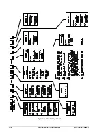
Page 12: ...1 4 BE1 60 General Information 9170700990 Rev D Figure 1 3 BE1 60 Style Chart...

Page 13: ...ly types available for the BE1 60 are summarized in Table 1 1 Table 1 1 Power Supply Types and Specifications Input Voltage Type Nominal Range Burden at Nominal O mid range 48 Vdc 24 to 150 Vdc 1 1 W...

Page 14: ...rcuits 1500 Vac or 2121 Vdc Surge Withstand Capability Qualified to IEEE C37 90 transient immunity and radiated susceptibility IEC 60255 5 impulse requirements and IEC60255 5 6 surge requirements Radi...

Page 15: ...s 2 1 SECTION 2 CONTROLS AND INDICATORS INTRODUCTION All BE1 60 controls and indicators are located on the relay front panel The controls and indicators are shown in Figure 2 1 and described in Table...

Page 16: ...for Circuit 1 and one for Circuit 2 When a fault occurs on Circuit 1 or Circuit 2 and the appropriate relay output changes state the corresponding target indicator illuminates Target indicators are ma...

Page 17: ...POWER SUPPLY SENSOR POWER SUPPLY STATUS TO INTERNAL CIRCUITRY POWER V LIMIT SETTING D2817 17 07 14 98 Figure 3 1 BE1 60 Function Block Diagram STEP DOWN TRANSFORMERS Voltage received from the power s...

Page 18: ...hanges state when the Circuit 2 output relay energizes Auxiliary outputs may be specified as normally open style X1X A1X XXX1X normally closed style X1X A1X XXX2X or single pole double throw SPDT styl...

Page 19: ...trip circuit Current Operated Targets A current operated target is triggered by closure of the corresponding output contact and the presence of at least 200 milliamperes of current flowing in the tri...

Page 20: ...3 4 BE1 60 Functional Description 9170700990 Rev D This page intentionally left blank...

Page 21: ...on a minimum current of 200 milliamperes must flow through the output trip circuit If a wiring insulation test is required remove the connection plugs and withdraw the relay from its case MOUNTING Bec...

Page 22: ...4 2 BE1 60 Installation 9170700990 Rev D Figure 4 1 S1 Cover Outline Dimensions Front View Figure 4 2 S1 Case Double Ended Semi Flush Mounting Outline Dimensions Side View...

Page 23: ...9170700990 Rev D BE1 60 Installation 4 3 Figure 4 3 S1 Case Double Ended Projection Mounting Outline Dimensions Side View...

Page 24: ...4 4 BE1 60 Installation 9170700990 Rev D Figure 4 4 S1 Case Double Ended Projection Mounting Panel Drilling Diagram Rear View...

Page 25: ...9170700990 Rev D BE1 60 Installation 4 5 Figure 4 5 S1 Case Semi Flush Mounting Panel Cutting Diagram Figure 4 6 S1 Case Double Ended Projection Mounting Outline Dimensions Rear View...

Page 26: ...ecting and energizing the relay Incorrect wiring may result in damage to the relay Except where noted connections should be made with wire no smaller than 14 AWG Connections for each of the six sensin...

Page 27: ...Sales Support at Basler Electric to coordinate repairs STORAGE This protective relay contains aluminum electrolytic capacitors which generally have a life expectancy in excess of 10 years at storage t...

Page 28: ...4 8 BE1 60 Installation 9170700990 Rev D This page intentionally left blank...

Page 29: ...arget indicators 3 Slowly increase the Circuit 1A input until the Circuit 2 output changes states Circuit 1A input should be between 125 and 127 Vac 4 Decrease the Circuit 1A input to 120 Vac Circuit...

Page 30: ...5 2 BE1 60 Testing 9170700990 Rev D This page intentionally left blank...

Page 31: ...ROUTE 143 BOX 269 HIGHLAND IL 62249 USA http www basler com info basler com PHONE 1 618 654 2341 FAX 1 618 654 2351...

Reviews: