1-4
General Information
BE1-67
APPLICATION
Without the ability to act on the direction of current flow, it is difficult to coordinate the settings of time
overcurrent relays on lines that interconnect a series of substations. Without this capability, either undesired
tripping of adjacent lines may occur. Or a fault may go undetected because of the high settings required by
non-directional relays.
With directional time overcurrent relays, the settings and time delays can be decreased and the undesired
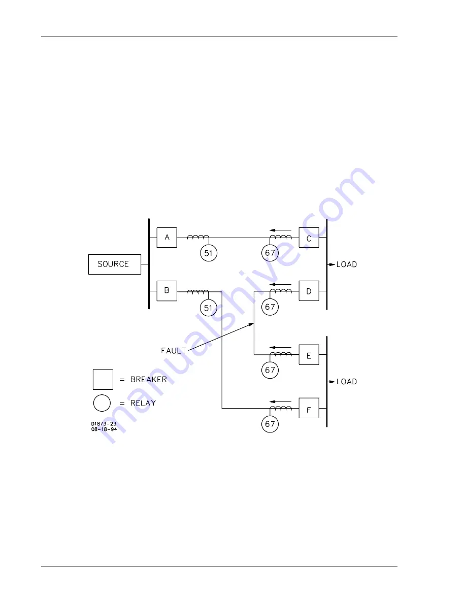
tripping eliminated. Figure 1-5 illustrates the use of directional overcurrent relays on a group of interconnected
distribution substations fed from a common source. In this example, non-directional overcurrent relays (51)
are used to protect the lines leaving the supply bus because there is only one source of fault current. However,
the breakers at the load buses (C, D, E and F) are protected by directional time overcurrent relays (67) to
prevent overtripping in the event of a fault. This will remove the faulted line and retain service to the connected
loads.
In the case where two sources of power can supply fault current, as shown in Figure 1-6, directional
overcurrent relays will need to be applied to each end of the protected lines to prevent undesired tripping.
Figure 1-5. Substations Fed From One Source
Summary of Contents for BE1-67
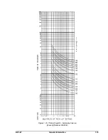
Page 23: ...BE1 67 General Information 1 17 Figure 1 13 Timing Type B2 Long Inverse Drawing Number 99 0931...
Page 26: ...1 20 General Information BE1 67 Figure 1 16 Timing Type B5 Inverse Drawing Number 99 0929...
Page 27: ...BE1 67 General Information 1 21 Figure 1 17 Timing Type B6 Very Inverse Drawing Number 99 0928...
Page 39: ...2 6 Human Machine Interface BE1 67 Figure 2 3 Location of Assemblies Controls and Indicators...
Page 47: ...4 2 Installation BE1 67 Figure 4 1 Outline Dimensions Front View...
Page 48: ...BE1 67 Installation 4 3 Figure 4 2 Outline Dimensions Rear View...
Page 49: ...4 4 Installation BE1 67 Figure 4 3 Outline Dimensions Side View Semi Flush Mounting...
Page 50: ...BE1 67 Installation 4 5 Figure 4 4 Outline Dimensions Side View Projection Mounting...
Page 51: ...4 6 Installation BE1 67 Figure 4 5 Panel Drilling Diagram Semi Flush Mounting...
Page 52: ...BE1 67 Installation 4 7 Figure 4 6 Panel Drilling Diagram Projection Mounting...
Page 54: ...BE1 67 Installation 4 9 Figure 4 8 Single Phase AC Connections...
Page 55: ...4 10 Installation BE1 67 Figure 4 9 Three Phase AC Connections...
Page 56: ...BE1 67 Installation 4 11 Figure 4 10 BE1 67 Single Phase Internal Connection Diagram...
Page 57: ...4 12 Installation BE1 67 Figure 4 11 BE1 67 Three Phase Internal Connection Diagram...
Page 62: ...BE1 67 Testing 5 5 Figure 5 3 Blank Polar Graph Form Figure 5 4 Blank Polar Graph Form...


