1-6
General Information
BE1-67
Using this relay under the stated conditions, there are five settings to be established:
!
Pickup of the timed element
!
Time dial
!
Timing characteristic
!
Torque angle
!
Pickup of the directional instantaneous unit
In arriving at a satisfactory setting for each variable, consideration must be given as to how the relay
coordinates with other upstream and downstream tripping devices. In particular, the time-current
characteristics of all relevant devices must be systematically considered for each fault condition that can
occur.
The ensuing analysis considers pickup settings first, followed by a detailed examination of the three scenarios
indicated in Figure 1-7 as faults L, M and N. These will be individually considered with regard to the five
settings listed previously and particularly the last four.
Pickup
When considering relay pickup, it is desirable to set the relay above the maximum load that the feeder is
expected to supply at any given time in the defined direction. Often this quantity is limited only by the breaker
size or the current carrying capacity of the line itself.
Returning to Figure 1-7, if it is assumed that the maximum lead current is 1,200 amperes for line AC and a
maximum CT ratio of 400:1, then:
Timed pickup setting = (1200)(1 ÷ 400)(1.25) = 3.75 amperes
(The 1.25 factor represents a margin of safety.)
Analysis Of Fault L
In Figure 1-7, assume the following fault L currents.
!
I
A(L)
= 3,000 amperes at an angle of -65 degrees
!
I
D(L)
= 6,400 amperes at an angle of -60 degrees
Based on these fault currents, the BE1-67 relay at A will pickup and begin to time out. But the primary concern
is that the relay at D trips before the one at A. This is accomplished by selecting the appropriate pickup, time
dial and characteristic for the 67
A
device. Note in Figure 1-8, illustration a, that the 67
D
characteristic curve
must be completely under the 67
A
curve for current greater than the 67
A
pickup point. A coordinating time
interval of0.2 to 0.5 seconds between the curves is usually recommended to accommodate breaker clearing
time plus a safety margin. The
Time Dial
should be set to provide this coordination margin.
Usually, time-characteristic curves are chosen to coordinate with existing system devices. Consequently, if
67
D
is extremely inverse, the 67
A
relay might well be set to the B7 curve (extremely inverse). To select the
curve, use the rotary switch behind the front panel of the relay.
The fault current level seen by I
A
(3,000 amperes) also confirms that the setting chosen (3.75 A x 400 = 1,500
primary amperes) is sensitive enough to detect remote end faults. This is assuming that the fault current is
not limited by fault impedance.
Analysis Of Fault M
In Figure 1-7, assume the following fault M currents:
!
I
A(M)
= 4,600 amperes at an angle of -60 degrees
!
I
E(M)
= 400 amperes at an angle of -65 degrees
Summary of Contents for BE1-67
Page 23: ...BE1 67 General Information 1 17 Figure 1 13 Timing Type B2 Long Inverse Drawing Number 99 0931...
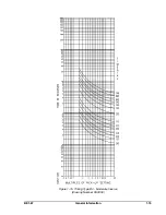
Page 26: ...1 20 General Information BE1 67 Figure 1 16 Timing Type B5 Inverse Drawing Number 99 0929...
Page 27: ...BE1 67 General Information 1 21 Figure 1 17 Timing Type B6 Very Inverse Drawing Number 99 0928...
Page 39: ...2 6 Human Machine Interface BE1 67 Figure 2 3 Location of Assemblies Controls and Indicators...
Page 47: ...4 2 Installation BE1 67 Figure 4 1 Outline Dimensions Front View...
Page 48: ...BE1 67 Installation 4 3 Figure 4 2 Outline Dimensions Rear View...
Page 49: ...4 4 Installation BE1 67 Figure 4 3 Outline Dimensions Side View Semi Flush Mounting...
Page 50: ...BE1 67 Installation 4 5 Figure 4 4 Outline Dimensions Side View Projection Mounting...
Page 51: ...4 6 Installation BE1 67 Figure 4 5 Panel Drilling Diagram Semi Flush Mounting...
Page 52: ...BE1 67 Installation 4 7 Figure 4 6 Panel Drilling Diagram Projection Mounting...
Page 54: ...BE1 67 Installation 4 9 Figure 4 8 Single Phase AC Connections...
Page 55: ...4 10 Installation BE1 67 Figure 4 9 Three Phase AC Connections...
Page 56: ...BE1 67 Installation 4 11 Figure 4 10 BE1 67 Single Phase Internal Connection Diagram...
Page 57: ...4 12 Installation BE1 67 Figure 4 11 BE1 67 Three Phase Internal Connection Diagram...
Page 62: ...BE1 67 Testing 5 5 Figure 5 3 Blank Polar Graph Form Figure 5 4 Blank Polar Graph Form...


