1-10
General Information
BE1-67
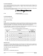
Current Sensing Input(s)
The unit is designed to operate from the secondary of a standard current transformer rated at 5 amperes. The
unit has a pickup adjustment range covering 0.5 to 12 amperes. The maximum continuous current rating of
each input is 20 amperes.
The one-second current rating of each input is 50 times tap or 500 amperes, whichever is less. Ratings at less
than one second are calculated as follows:
where
I = Maximum current
T = Time that current flows (in seconds)
Current Sensing Burden
Less than 0.01 ohm per input.
Time Overcurrent Pickup
Range
Pickup of the time overcurrent elements is continuously adjustable over theentire range of 0.5 to 12 amperes.
(See Table 1-3.) This is accomplished through the selection of external connections (LOW RANGE 0.5 to 4.0
amperes; HIGH RANGE 1.5 to 12 amperes), a TAP selector switch and TAP CAL adjustment.
A TAP RANGE plate is provided on the front panel to define the external connections and the range of
adjustment available when the unit is installed in the protection panel.
Table 1-3. Sensing Input Ranges And Connections
TAP Range
Plate or
Pickup
TAP Selector
Current Sensing
Terminals
A
B
C
D
E
F
G
H
I
J
N
A
N
B
N
C
Single-Phase
High
2.25
3.00
4.50
5.25
6.75
7.50
9.00
9.75
11.2
5
12.0
0
8,7
-----
-----
Low
0.75
1.00
1.50
1.75
2.25
2.50
3.00
3.25
3.75
4.00
9,7
-----
-----
Three-Phase
High
2.25
3.00
4.50
5.25
6.75
7.50
9.00
9.75
11.2
5
12.0
0
8,7
14,15
17,18
Low
0.75
1.00
1.50
1.75
2.25
2.50
3.00
3.25
3.75
4.00
9,7
13,15
16,18
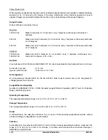
Pickup Accuracy
The accuracy of the pickup setting established by the TAP selector switch when the TAP CAL adjustment is
fully clockwise, is ±5%. The TAP CAL adjustment allows the relay to be set anywhere between the value
established by the TAP selector switch position and the next lower setting position.
The setting of the relay is repeatable within ±2%.
Dropout Ratio
Better than 95% of the established pickup level.
Summary of Contents for BE1-67
Page 23: ...BE1 67 General Information 1 17 Figure 1 13 Timing Type B2 Long Inverse Drawing Number 99 0931...
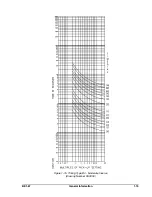
Page 26: ...1 20 General Information BE1 67 Figure 1 16 Timing Type B5 Inverse Drawing Number 99 0929...
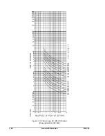
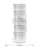
Page 27: ...BE1 67 General Information 1 21 Figure 1 17 Timing Type B6 Very Inverse Drawing Number 99 0928...
Page 39: ...2 6 Human Machine Interface BE1 67 Figure 2 3 Location of Assemblies Controls and Indicators...
Page 47: ...4 2 Installation BE1 67 Figure 4 1 Outline Dimensions Front View...
Page 48: ...BE1 67 Installation 4 3 Figure 4 2 Outline Dimensions Rear View...
Page 49: ...4 4 Installation BE1 67 Figure 4 3 Outline Dimensions Side View Semi Flush Mounting...
Page 50: ...BE1 67 Installation 4 5 Figure 4 4 Outline Dimensions Side View Projection Mounting...
Page 51: ...4 6 Installation BE1 67 Figure 4 5 Panel Drilling Diagram Semi Flush Mounting...
Page 52: ...BE1 67 Installation 4 7 Figure 4 6 Panel Drilling Diagram Projection Mounting...
Page 54: ...BE1 67 Installation 4 9 Figure 4 8 Single Phase AC Connections...
Page 55: ...4 10 Installation BE1 67 Figure 4 9 Three Phase AC Connections...
Page 56: ...BE1 67 Installation 4 11 Figure 4 10 BE1 67 Single Phase Internal Connection Diagram...
Page 57: ...4 12 Installation BE1 67 Figure 4 11 BE1 67 Three Phase Internal Connection Diagram...
Page 62: ...BE1 67 Testing 5 5 Figure 5 3 Blank Polar Graph Form Figure 5 4 Blank Polar Graph Form...

