5-6
Testing
BE1-67
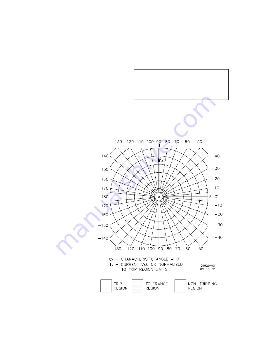
In the polar graphs associated with the
procedures for Directional Verification:
I
= Measured current at unity power factor
I
Z
= Fault current
V
= Quadrature or polarizing voltage
Figure 5-5.
"
= 0°
There are two types of CHARACTERISTIC ANGLE adjustments available with this unit:
(1)
A potentiometer capable of adjusting this angle over the range of 0° to 90°.
(2)
A 4-position switch with settings of 30°, 45°, 60° and 75°.
If a potentiometer is provided, use
Procedure 1
. If a switch is supplied, use
Procedure 2
.
Procedure 1
(For use with continuously adjustable CHARACTERISTIC ANGLE, options 3-1, 3-3, 3-5, and 3-6.)
Step 1.
Perform the preliminary setup.
Step 2.
Adjust the input voltage source for 120 volts at
a phase angle of 0°.
Step 3 .
Adjust the input current Source for 1.0 amperes
(LOW range ) or 3.0 amperes (HIGH range) at a phase angle of +90° (90° leading).
Result:
The INHIBIT LED indicator should be extinguished and the (appropriate phase) timing LED
OFF. If not, the current or voltage connections are reversed and should be corrected.
Step 4.
Vary the phase angle of
the input current through
360° and record the phase
angles within which the
INHIBIT LED is OFF.
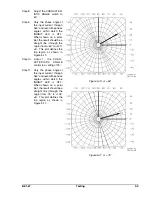
When shown on a polar
plot, the result should be a
straight line (through the
origin) from 0° to 180° ±5°.
This plot defines the trip
region as shown in Figure
5-5. The trip region is
shown as the lightly
shaded area and the
tolerance region as the
more densely shaded
region.
Step 5.
Rotate
the CHARAC-
TERISTIC ANGLE control
to the maximum setting.
Step 6.
Vary the phase angle of
the input current through
360° and record the phase
angles within which the
INHIBIT LED is OFF.
When shown on a polar
plot, the result should be a
straight line (through the
origin ) from -90° to +90°
±5°. This plot defines the
trip region as shown in
Figure 5-6.
Summary of Contents for BE1-67
Page 23: ...BE1 67 General Information 1 17 Figure 1 13 Timing Type B2 Long Inverse Drawing Number 99 0931...
Page 26: ...1 20 General Information BE1 67 Figure 1 16 Timing Type B5 Inverse Drawing Number 99 0929...
Page 27: ...BE1 67 General Information 1 21 Figure 1 17 Timing Type B6 Very Inverse Drawing Number 99 0928...
Page 39: ...2 6 Human Machine Interface BE1 67 Figure 2 3 Location of Assemblies Controls and Indicators...
Page 47: ...4 2 Installation BE1 67 Figure 4 1 Outline Dimensions Front View...
Page 48: ...BE1 67 Installation 4 3 Figure 4 2 Outline Dimensions Rear View...
Page 49: ...4 4 Installation BE1 67 Figure 4 3 Outline Dimensions Side View Semi Flush Mounting...
Page 50: ...BE1 67 Installation 4 5 Figure 4 4 Outline Dimensions Side View Projection Mounting...
Page 51: ...4 6 Installation BE1 67 Figure 4 5 Panel Drilling Diagram Semi Flush Mounting...
Page 52: ...BE1 67 Installation 4 7 Figure 4 6 Panel Drilling Diagram Projection Mounting...
Page 54: ...BE1 67 Installation 4 9 Figure 4 8 Single Phase AC Connections...
Page 55: ...4 10 Installation BE1 67 Figure 4 9 Three Phase AC Connections...
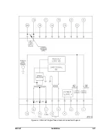
Page 56: ...BE1 67 Installation 4 11 Figure 4 10 BE1 67 Single Phase Internal Connection Diagram...
Page 57: ...4 12 Installation BE1 67 Figure 4 11 BE1 67 Three Phase Internal Connection Diagram...
Page 62: ...BE1 67 Testing 5 5 Figure 5 3 Blank Polar Graph Form Figure 5 4 Blank Polar Graph Form...


