1-2
BE1-67N General Information
9190700990 Rev F
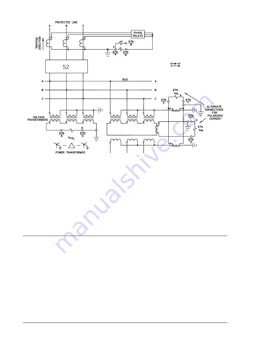
Figure 1-2. Zero Sequence Polarizing (Three-Winding Transformer)
Zero Sequence Voltage
Zero sequence voltage polarization is preferred for higher ground source impedances. Refer to Figures 1-
1 and 1-2 for relay connections that obtain zero sequence voltage (3V
0
) from a set of grounded wye-
broken delta voltage transformers. The voltage polarized relay has a directional polarization adjustment to
match the impedance angle of the protected line to the characteristic angle of the relay. This is the angle
about which the directional angle is centered. A choice of line angles allows the relay to be adjusted to
include the resistance component of the ground fault.
Dual Zero Sequence Current and Voltage
Dual polarization is preferred where ground source impedance varies, or to provide redundant
polarization. Dual polarization is achieved using a polarizing signal that is the phasor sum of the current
and voltage polarizing signals.
OUTPUT CONTACTS
BE1-67N relays have the following output contacts: relay status alarm (relay fail), tripping, and auxiliary
(optional).
Relay Status Alarm
A relay status alarm output contact (relay fail) indicates that proper voltages are not being supplied to the
internal relay circuitry or that the microprocessor self-diagnostics has detected an error. This alarm output
contact is normally closed.
Tripping
Normally open or normally closed tripping contacts are included for each function within the relay.
Configuration of these contacts is defined by the relay style number. These output contacts are used with
optionally selected target indicator circuits.
Summary of Contents for BE1-67N
Page 2: ......
Page 6: ...iv BE1 67N Introduction 9190700990 Rev F This page intentionally left blank...
Page 8: ...vi BE1 67N Introduction 9190700990 Rev F This page intentionally left blank...
Page 10: ...ii BE1 67N General Information 9190700990 Rev F This page intentionally left blank...
Page 18: ...1 8 BE1 67N General Information 9190700990 Rev F This page intentionally left blank...
Page 20: ...ii BE1 67N Controls and Indicators 9190700990 Rev F This page intentionally left blank...
Page 26: ...ii BE1 67N Functional Description 9190700990 Rev F This page intentionally left blank...
Page 34: ...ii BE1 67N Installation 9190700990 Rev F This page intentionally left blank...
Page 39: ...9190700990 Rev F BE1 67N Installation 4 5 Figure 4 4 Case Dimensions Rear View...
Page 43: ...9190700990 Rev F BE1 67N Installation 4 9 Figure 4 7 Typical Internal Connections...
Page 46: ...4 12 BE1 67N Installation 9190700990 Rev F This page intentionally left blank...
Page 48: ...ii BE1 67N Testing 9190700990 Rev F This page intentionally left blank...
Page 58: ...ii BE1 67N Characteristic Curves 9190700990 Rev F This page intentionally left blank...
Page 72: ...A 14 BE1 67N Characteristic Curves 9190700990 Rev F This page intentionally left blank...
Page 74: ...B 2 BE1 67N Polar Graph Forms 9190700990 Rev F This page intentionally left blank...


