background image

Summary of Contents for BE1-67N

Page 1: ...INSTRUCTION MANUAL FOR GROUND DIRECTIONAL OVERCURRENT RELAY BE1 67N Publication 9190700990 Revision F 08 07...

Page 2: ......

Page 3: ...Controls and Indicators Functional Description Installation Testing WARNING To avoid personal injury or equipment damage only qualified personnel should perform the procedures in this manual NOTE Be s...

Page 4: ...operation The availability and design of all features and options are subject to modification without notice Should further information be required contact Basler Electric BASLER ELECTRIC ROUTE 143 B...

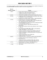
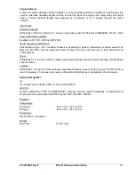
Page 5: ...rrected instantaneous overcurrent maximum operating times listed in the specifications and Table 3 5 Corrected the polarizing voltage input burden listed in the specifications Removed the shorting bar...

Page 6: ...iv BE1 67N Introduction 9190700990 Rev F This page intentionally left blank...

Page 7: ...v CONTENTS SECTION 1 GENERAL INFORMATION 1 1 SECTION 2 CONTROLS AND INDICATORS 2 1 SECTION 3 FUNCTIONAL DESCRIPTION 3 1 SECTION 4 INSTALLATION 4 1 SECTION 5 TESTING 5 1 APPENDIX A CHARACTERISTIC CURVE...

Page 8: ...vi BE1 67N Introduction 9190700990 Rev F This page intentionally left blank...

Page 9: ...D STYLE NUMBER 1 3 Style Number Example 1 3 SPECIFICATIONS 1 4 Current Sensing IO Inputs 1 4 Frequency 1 4 Polarizing Current I0 1 5 Polarizing Voltage V0 1 5 Directional Unit 1 5 Time Overcurrent 1 5...

Page 10: ...ii BE1 67N General Information 9190700990 Rev F This page intentionally left blank...

Page 11: ...antities for polarization Zero sequence current Zero sequence voltage Dual zero sequence current and voltage The polarizing quantity is field selectable using a switch mounted on the analog circuit bo...

Page 12: ...ro Sequence Current and Voltage Dual polarization is preferred where ground source impedance varies or to provide redundant polarization Dual polarization is achieved using a polarizing signal that is...

Page 13: ...WER SUPPLY OPTIONS Various power supply options are available to allow the BE1 67N relay to be used with standard supply voltages See the style chart for details POWER UP DELAY A power up delay timer...

Page 14: ...rent Sensing IO Inputs Pickup Adjustment Range Range 1 and 2 0 25 to 6 0 Aac Range 3 and 4 0 05 to 1 2 Aac Current Rating Sensing Input Range 1 and 2 Continuous Rating 7 5 Aac 5 Minute Rating 20 Aac 1...

Page 15: ...Angle Characteristic angle is switch selectable to 0 or 60 Characteristic angle accuracy is 5 for V0 inputs below 30 Vac and 10 for V0 inputs greater than 30 Vac Directional Closing Band Directional...

Page 16: ...y operating power may be obtained from a wide variety of external sources When ordering any one of five internal power supply types may be selected to match the operating power voltage level available...

Page 17: ...om frequencies centered around 144 MHz and 440 MHz with the antenna located 6 inches 150 mm from the relay in both horizontal and vertical planes Shock Withstands 15 G in each of three mutually perpen...

Page 18: ...1 8 BE1 67N General Information 9190700990 Rev F This page intentionally left blank...

Page 19: ...DIGITAL CIRCUIT BOARD CONTROLS 2 3 MOTHER CIRCUIT BOARD CONTROLS 2 4 Figures Figure 2 1 Front Panel Controls and Indicators 2 1 Figure 2 2 Analog and Digital Circuit Board Controls 2 3 Figure 2 3 Aux...

Page 20: ...ii BE1 67N Controls and Indicators 9190700990 Rev F This page intentionally left blank...

Page 21: ...ocated on the front panel and Analog Digital and Mother circuit board assemblies FRONT PANEL CONTROLS AND INDICATORS Front panel HMI components are illustrated in Figure 2 1 and described in Table 2 1...

Page 22: ...pply current or voltage to the relay sensing inputs One switch is provided for each output contact The recessed switches are operated by inserting a nonconductive rod through the front panel switch ho...

Page 23: ...Source Select Switch S3 This assembly located on the Analog circuit board consists of two switches The left hand switch enables zero sequence voltage polarization and the right hand switch enables ze...

Page 24: ...ct Switch Location S1 enables the auxiliary output contact if equipped to operate in parallel with any combination of tripping outputs Table 2 3 lists each tripping output and the S1 position that cau...

Page 25: ...put Contacts 3 5 PUSH TO ENERGIZE OUTPUT SWITCHES 3 6 POWER SUPPLY 3 6 TARGETS 3 6 Internally Operated Targets 3 6 Current Operated Targets 3 6 Figures Figure 3 1 Function Block Diagram 3 1 Figure 3 2...

Page 26: ...ii BE1 67N Functional Description 9190700990 Rev F This page intentionally left blank...

Page 27: ...ve inputs from the 5 Aac sensing input range 1 or 2 or 1 Aac sensing input range 3 or 4 nominal secondary of standard transformers Input transformers for the sensed measured current Iop are tapped so...

Page 28: ...he relay pickup setting will be within 5 of the Tap Selector switch setting VOLTAGE SENSING The relay receives a polarized voltage input VO from the secondary windings of standard potential transforme...

Page 29: ...f V0 0 75 volts applied to the relay To enable the directional instantaneous overcurrent element the level of V0 applied to the relay must be 4 volts or more Figure 3 3 shows the phase relationship be...

Page 30: ...e This simply means that the directional characteristic is in the center of the total trip region when V0 leads the directional characteristic by 60o OVERCURRENT ELEMENTS The BE1 67N relay has a direc...

Page 31: ...self diagnostics function has detected an error A case mounted shorting bar places a short circuit across terminals 19 and 20 when the relay draw out assembly is removed from the case Tripping Output...

Page 32: ...consist of red LED indicators located on the relay front panel A latched target is reset by operating the target reset switch on the front panel If relay operating power is lost any illuminated latch...

Page 33: ...4 2 Panel Drilling Diagram Projection Mounting 4 3 Figure 4 3 Cover Dimensions Front View 4 4 Figure 4 4 Case Dimensions Rear View 4 5 Figure 4 5 Case and Cover Dimensions Semi Flush Mounting Side Vi...

Page 34: ...ii BE1 67N Installation 9190700990 Rev F This page intentionally left blank...

Page 35: ...ns For proper current operated target operation a minimum current of 200 milliamperes must flow through the output trip circuit If a wiring insulation test is required remove the connection plugs and...

Page 36: ...4 2 BE1 67N Installation 9190700990 Rev F Figure 4 1 Panel Cutting and Drilling Diagram Semi Flush Mounting...

Page 37: ...9190700990 Rev F BE1 67N Installation 4 3 Figure 4 2 Panel Drilling Diagram Projection Mounting...

Page 38: ...4 4 BE1 67N Installation 9190700990 Rev F P0002 14 08 10 01 Figure 4 3 Cover Dimensions Front View...

Page 39: ...9190700990 Rev F BE1 67N Installation 4 5 Figure 4 4 Case Dimensions Rear View...

Page 40: ...4 6 BE1 67N Installation 9190700990 Rev F D2856 03 06 15 99 Figure 4 5 Case and Cover Dimensions Semi Flush Mounting Side View...

Page 41: ...BE1 67N Installation 4 7 D2856 21 06 15 99 DETAIL A A SHOWING THE ADDITION OF WASHERS OVER THE BOSS TO TIGHTEN THE RELAY AGAINST THE PANEL CASE PANEL Figure 4 6 Case and Cover Dimensions Projection Mo...

Page 42: ...and energizing the relay Incorrect wiring may result in damage to the relay Except where noted connections should be made with wire no smaller than 14 AWG Internal relay connections are shown in Figu...

Page 43: ...9190700990 Rev F BE1 67N Installation 4 9 Figure 4 7 Typical Internal Connections...

Page 44: ...4 10 BE1 67N Installation 9190700990 Rev F Figure 4 8 Typical Sensing Input Connections Two Winding Transformer Figure 4 9 Typical Sensing Input Connections Three Winding Transformer...

Page 45: ...l Sales Support at Basler Electric to coordinate repairs STORAGE This protective relay contains aluminum electrolytic capacitors which generally have a life expectancy in excess of 10 years at storage...

Page 46: ...4 12 BE1 67N Installation 9190700990 Rev F This page intentionally left blank...

Page 47: ...ure 5 6 Timing Curve Verification 5 8 Figures Figure 5 1 Typical Test Connections 5 1 Figure 5 2 Trip Zone Using VO as Polarizing Source Char Angle 0 5 3 Figure 5 3 Trip Zone Using VO as Polarizing So...

Page 48: ...ii BE1 67N Testing 9190700990 Rev F This page intentionally left blank...

Page 49: ...preliminary test setup BE1 67N operational testing consists of a time overcurrent pickup test an instantaneous overcurrent pickup test directional and non directional VO directional verification and I...

Page 50: ...low range or 1 125 Aac high range This verifies the pickup accuracy of the tap A setting 6 If verification of the remaining Tap Selector positions is desired adjust the Tap Selector to its next clock...

Page 51: ...IO to 1 8 Aac 9 Confirm that the directional instantaneous trip output contacts open 10 Rotate the Directional Instantaneous Overcurrent control fully clockwise VO Directional Verification For the fol...

Page 52: ...as the phase angle relationship between sensing quantities The results should be recorded on polar graph paper to understand the significance of the results Blank polar graph forms are provided in Ap...

Page 53: ...g characteristic Use the Time Overcurrent Characteristic Curve Selector switch locator C of Figure 2 2 to select the desired characteristic Table 5 2 Expected Timing at Five Times Pickup Expected Time...

Page 54: ...cedure Following a preliminary test setup BE1 67N operational testing consists of a time overcurrent pickup test an instantaneous overcurrent pickup test directional and non directional VO directional...

Page 55: ...the Preliminary Test Setup before proceeding with time overcurrent pickup testing 2 Adjust the Non Directional Instantaneous Overcurrent control fully clockwise 3 Apply 0 4 Aac input current IO 4 Slo...

Page 56: ...at a phase angle of 0 3 With the IO current source set at 0 2 Aac low range or 0 4 Aac high range and the Characteristic Angle switch set at 0 vary the phase angle of the VO input through 360 and not...

Page 57: ...ch Position 2 A 5 Figure A 5 Timing Type B5 Inverse Switch Position 4 A 6 Figure A 6 Timing Type B6 Very Inverse Switch Position 6 A 7 Figure A 7 Timing Type B7 Extremely Inverse Switch Position 7 A 8...

Page 58: ...ii BE1 67N Characteristic Curves 9190700990 Rev F This page intentionally left blank...

Page 59: ...selector switch position Table A 1 Characteristic Curves and Switch Positions Switch Position Characteristic Curve Characteristic Description Figure 3 B1 Short Inverse A 1 1 B2 Long Inverse A 2 5 B3...

Page 60: ...A 2 BE1 67N Characteristic Curves 9190700990 Rev F Figure A 1 Timing Type B1 Short Inverse Switch Position 3...

Page 61: ...9190700990 Rev F BE1 67N Characteristic Curves A 3 Figure A 2 Timing Type B2 Long Inverse Switch Position 1...

Page 62: ...A 4 BE1 67N Characteristic Curves 9190700990 Rev F Figure A 3 Timing Type B3 Definite Time Switch Position 5...

Page 63: ...9190700990 Rev F BE1 67N Characteristic Curves A 5 Figure A 4 Timing Type B4 Moderate Inverse Switch Position 2...

Page 64: ...A 6 BE1 67N Characteristic Curves 9190700990 Rev F Figure A 5 Timing Type B5 Inverse Switch Position 4...

Page 65: ...9190700990 Rev F BE1 67N Characteristic Curves A 7 Figure A 6 Timing Type B6 Very Inverse Switch Position 6...

Page 66: ...A 8 BE1 67N Characteristic Curves 9190700990 Rev F Figure A 7 Timing Type B7 Extremely Inverse Switch Position 7...

Page 67: ...9190700990 Rev F BE1 67N Characteristic Curves A 9 Figure A 8 Timing Type E2 BS 142 Long Inverse Switch Position 8...

Page 68: ...A 10 BE1 67N Characteristic Curves 9190700990 Rev F Figure A 9 Timing Type E4 BS 132 Inverse Switch Position 9...

Page 69: ...9190700990 Rev F BE1 67N Characteristic Curves A 11 Figure A 10 Timing Type E5 BS 142 Inverse Switch Position A...

Page 70: ...A 12 BE1 67N Characteristic Curves 9190700990 Rev F D0334 03 Figure A 11 Timing Type E6 BS 142 Very Inverse Switch Position B...

Page 71: ...9190700990 Rev F BE1 67N Characteristic Curves A 13 Figure A 12 Timing Type E7 BS 142 Extremely Inverse Switch Position C D E F...

Page 72: ...A 14 BE1 67N Characteristic Curves 9190700990 Rev F This page intentionally left blank...

Page 73: ...E1 67N Polar Graph Forms B 1 APPENDIX B POLAR GRAPH FORMS These polar graph forms may be used to record and interpret the results of the VO and IO directional verification test procedures provided in...

Page 74: ...B 2 BE1 67N Polar Graph Forms 9190700990 Rev F This page intentionally left blank...

Page 75: ...ROUTE 143 BOX 269 HIGHLAND IL 62249 USA http www basler com info basler com PHONE 1 618 654 2341 FAX 1 618 654 2351...

Reviews: