3-2
BE1-67N Functional Description
9190700990 Rev F
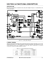
Outputs from the sensing input transformers are applied to a scaling circuit that converts each of the input
currents to a dc voltage level. Scaling is controlled by the Tap Selector switch and the Tap Calibration
control on the front panel.
The Tap Selector switch is a 10-position rotary switch that controls the relay settings listed in Tables 3-2
and 3-3. The values of current listed are obtained with the Tap Calibration control adjusted fully
clockwise. Range is determined by the relay current sensing input connections. When the Tap Calibration
control is in the fully clockwise position, the relay pickup setting will be within
±
5% of the Tap Selector
switch setting.
Table 3-2. Sensing Input Range and Setting for 1 Aac Secondary
Tap Selector Switch Position
Nominal
Range
A B C D E F G H I J
I
op
Terminals
High 0.225 0.300 0.450 0.453 0.675 0.750 0.900 0.925 1.125 1.200 7
and
8
Low
0.075 0.100 0.150 0.175 0.225 0.250 0.300 0.325 0.375 0.400 7
and
9
Table 3-3. Sensing Input Range and Setting for 5 Aac Secondary
Tap Selector Switch Position
Nominal
Range
A B C D E F G H I J
I
op
Terminals
High 1.125 1.500 2.250 2.625 3.375 3.750 4.500 4.875 5.625 6.000 7
and
8
Low
0.375 0.500 0.750 0.875 1.125 1.250 1.500 1.625 1.875 2.000 7
and
9
The Tap Calibration control provides continuous adjustment between a selected setting of the Tap
Selector switch and the next lower setting. When the Tap Calibration control is adjusted fully clockwise,
the relay pickup setting will be within
±
5% of the Tap Selector switch setting.
VOLTAGE SENSING
The relay receives a polarized voltage input (V
O
) from the secondary windings of standard potential
transformers or coupling capacitor potential devices. These components supply up to 240 volts (line to
neutral) for a 50/60 hertz nominal system frequency.
DIRECTIONAL ELEMENT
The directional element determines when the monitored power system quantities have the proper phase
relationship for tripping. The BE1-67N has three types of switch-selectable, directional capabilities: zero
sequence current polarization, zero sequence voltage polarization, and dual zero sequence current and
voltage polarization. Polarizing Source Select Switch S3, located on the Analog circuit board, is used to
select the desired directional capability.
Zero Sequence Current Polarization
The zero sequence current polarizing unit is capable of detecting the phase relationship between the zero
sequence current (I
0
) and the sensed, measured current (I
op
) for the relay. This unit is insensitive to third
and higher harmonics.
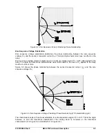
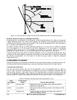
An enabling output from the zero sequence current unit is given when the phase angle between I
0
and I
op
is 75
°
or less as shown in Figure 3-2. The total trip region (shaded area in Figures 3-2, 3-3, and 3-4) is
150
°
.
To allow operation of the time overcurrent element, the level of I
0
applied to the directional element must
be in excess of 0.2 amperes.
To allow operation of the directional instantaneous overcurrent element, the level of I
0
applied to the
directional element must be in excess of an internal, user adjustable threshold. The range of this setting is
0.75 to 2 amperes. The default, factory setting is 2 amperes.
Summary of Contents for BE1-67N
Page 2: ......
Page 6: ...iv BE1 67N Introduction 9190700990 Rev F This page intentionally left blank...
Page 8: ...vi BE1 67N Introduction 9190700990 Rev F This page intentionally left blank...
Page 10: ...ii BE1 67N General Information 9190700990 Rev F This page intentionally left blank...
Page 18: ...1 8 BE1 67N General Information 9190700990 Rev F This page intentionally left blank...
Page 20: ...ii BE1 67N Controls and Indicators 9190700990 Rev F This page intentionally left blank...
Page 26: ...ii BE1 67N Functional Description 9190700990 Rev F This page intentionally left blank...
Page 34: ...ii BE1 67N Installation 9190700990 Rev F This page intentionally left blank...
Page 39: ...9190700990 Rev F BE1 67N Installation 4 5 Figure 4 4 Case Dimensions Rear View...
Page 43: ...9190700990 Rev F BE1 67N Installation 4 9 Figure 4 7 Typical Internal Connections...
Page 46: ...4 12 BE1 67N Installation 9190700990 Rev F This page intentionally left blank...
Page 48: ...ii BE1 67N Testing 9190700990 Rev F This page intentionally left blank...
Page 58: ...ii BE1 67N Characteristic Curves 9190700990 Rev F This page intentionally left blank...
Page 72: ...A 14 BE1 67N Characteristic Curves 9190700990 Rev F This page intentionally left blank...
Page 74: ...B 2 BE1 67N Polar Graph Forms 9190700990 Rev F This page intentionally left blank...


