3-4
BE1-67N Functional Description
9190700990 Rev F
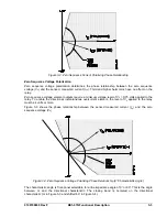
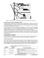
Figure 3-4. Zero Sequence Voltage Polarizing Phase Relationship (60
°
Characteristic Angle)
Dual Zero Sequence Current and Voltage Polarization
Dual polarizing is a combination of zero sequence current polarizing (Figure 3-2) and/or zero sequence
voltage polarizing (Figure 3-3). When both quantities are available, the two polarizing quantities are
combined at the electronics logic level to produce a sum of the two quantities which is then compared to
the I
op
quantity to establish the total trip region.
As system conditions change, one of the polarizing quantities (V
0
or I
0
) may not be of sufficient magnitude
(I
0
≥
0.2 amperes or V
0
≥
0.75 volts) for use in the comparison to I
op
. For instance, if a potential
transformer fuse is blown and V
0
is not available, the comparison to I
op
is done with I
0
only. When dual
polarization is selected, either V
0
or I
0
or both as stated above, can be used in the comparison.
If dual polarizing is selected and the 60
o
setting is selected, only the V
0
polarization is affected as shown
in Figure 3-4 and dual polarizing comparison still functions as described above. This simply means that
the directional characteristic is in the center of the total trip region when V
0
leads the directional
characteristic by 60
o
.
OVERCURRENT ELEMENTS
The BE1-67N relay has a directional, controlled time overcurrent element and may optionally include non-
directional and/or directional instantaneous overcurrent elements as specified by the style number.
Time Overcurrent Element
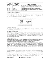
The time overcurrent element has all of the standard time current characteristics listed in Table 3-4.
These 12 time overcurrent characteristics are available to aid in the coordination of the BE1-67N with
other protective devices in the system. Seven of the characteristics are standard in North America and
five are compatible with British or IEC standard requirements. Time Overcurrent Characteristic Curve
Selector Switch S6, located on the Digital circuit board, is used to select the time curve characteristic.
Table 3-4. Selection Considerations for Characteristic Curves
Style
Designation
Characteristic
Shape
Special Characteristics
B1
Short Inverse
Relatively short time, desirable where preserving system
stability is a critical factor.
B2, E2
Long Inverse
Provides protection for starting motors and overloads of short
duration.
B3
Definite Time
Fixed time delay according to time dial setting. Useful for
sequential tripping schemes.
Summary of Contents for BE1-67N
Page 2: ......
Page 6: ...iv BE1 67N Introduction 9190700990 Rev F This page intentionally left blank...
Page 8: ...vi BE1 67N Introduction 9190700990 Rev F This page intentionally left blank...
Page 10: ...ii BE1 67N General Information 9190700990 Rev F This page intentionally left blank...
Page 18: ...1 8 BE1 67N General Information 9190700990 Rev F This page intentionally left blank...
Page 20: ...ii BE1 67N Controls and Indicators 9190700990 Rev F This page intentionally left blank...
Page 26: ...ii BE1 67N Functional Description 9190700990 Rev F This page intentionally left blank...
Page 34: ...ii BE1 67N Installation 9190700990 Rev F This page intentionally left blank...
Page 39: ...9190700990 Rev F BE1 67N Installation 4 5 Figure 4 4 Case Dimensions Rear View...
Page 43: ...9190700990 Rev F BE1 67N Installation 4 9 Figure 4 7 Typical Internal Connections...
Page 46: ...4 12 BE1 67N Installation 9190700990 Rev F This page intentionally left blank...
Page 48: ...ii BE1 67N Testing 9190700990 Rev F This page intentionally left blank...
Page 58: ...ii BE1 67N Characteristic Curves 9190700990 Rev F This page intentionally left blank...
Page 72: ...A 14 BE1 67N Characteristic Curves 9190700990 Rev F This page intentionally left blank...
Page 74: ...B 2 BE1 67N Polar Graph Forms 9190700990 Rev F This page intentionally left blank...


