3-6
BE1-67N Functional Description
9190700990 Rev F
PUSH-TO-ENERGIZE OUTPUT SWITCHES
A pushbutton (one for each tripping function) energizes the corresponding output relay for testing
purposes. To prevent accidental operation of these switches, they are recessed behind the front panel
and are accessed by inserting a thin, non-conducting rod through access holes in the panel. Control
power must be applied to energize the output relays but application of sensing voltage and current is not
necessary.
POWER SUPPLY
Operating power for the relay circuitry is supplied by a wide range, electrically isolated, low-burden power
supply. Power supply operating power is not polarity sensitive. The front panel power LED and power
supply status output indicate when the power supply is operating. Power supply specifications are listed
in Table 1-2.
TARGETS
Target indicators are optional components selected when a relay is ordered. The electronically latched
and reset targets consist of red LED indicators located on the relay front panel. A latched target is reset
by operating the target reset switch on the front panel. If relay operating power is lost, any illuminated
(latched) targets are extinguished. When relay operating power is restored, the previously latched targets
are restored to their latched state.
A relay can be equipped with either internally operated targets or current operated targets.
Internally Operated Targets
Outputs from the overcurrent elements are directly applied to drive the appropriate target indicator. Each
indicator is illuminated regardless of the current level in the trip circuit.
Current Operated Targets
A current operated target is triggered by closure of the corresponding output contact and the presence of
at least 200 milliamperes of current flowing in the trip circuit.
Note that the front panel function targets (
TIMED, INST 1,
etc.) may be either internally or current
operated.
NOTE
Prior to August 2007, BE1-67N target indicators consisted of magnetically
latched, disc indicators. These mechanically latched target indicators have been
replaced by the electronically latched LED targets in use today.
Summary of Contents for BE1-67N
Page 2: ......
Page 6: ...iv BE1 67N Introduction 9190700990 Rev F This page intentionally left blank...
Page 8: ...vi BE1 67N Introduction 9190700990 Rev F This page intentionally left blank...
Page 10: ...ii BE1 67N General Information 9190700990 Rev F This page intentionally left blank...
Page 18: ...1 8 BE1 67N General Information 9190700990 Rev F This page intentionally left blank...
Page 20: ...ii BE1 67N Controls and Indicators 9190700990 Rev F This page intentionally left blank...
Page 26: ...ii BE1 67N Functional Description 9190700990 Rev F This page intentionally left blank...
Page 34: ...ii BE1 67N Installation 9190700990 Rev F This page intentionally left blank...
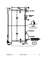
Page 39: ...9190700990 Rev F BE1 67N Installation 4 5 Figure 4 4 Case Dimensions Rear View...
Page 43: ...9190700990 Rev F BE1 67N Installation 4 9 Figure 4 7 Typical Internal Connections...
Page 46: ...4 12 BE1 67N Installation 9190700990 Rev F This page intentionally left blank...
Page 48: ...ii BE1 67N Testing 9190700990 Rev F This page intentionally left blank...
Page 58: ...ii BE1 67N Characteristic Curves 9190700990 Rev F This page intentionally left blank...
Page 72: ...A 14 BE1 67N Characteristic Curves 9190700990 Rev F This page intentionally left blank...
Page 74: ...B 2 BE1 67N Polar Graph Forms 9190700990 Rev F This page intentionally left blank...


