9190700990 Rev F
BE1-67N Testing
5-1
SECTION 5
•
TESTING
INTRODUCTION
This section provides procedures for testing the operation of BE1-67N relays. Separate test procedures
are provided for relays with sensing input ranges 1 and 2 and sensing input ranges 3 and 4. Use the
procedures that correspond to the sensing input range of your relay.
TEST PROCEDURES FOR SENSING INPUT RANGES 1 AND 2
The following paragraphs contain procedures for verifying the operation and timing curves of a BE1-67N
relay with sensing input range 1 or 2.
Operational Test Procedure
Following a preliminary test setup, BE1-67N operational testing consists of a time overcurrent pickup test,
an instantaneous overcurrent pickup test (directional and non-directional), V
O
directional verification, and
I
O
directional verification.
Preliminary Test Setup
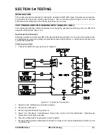
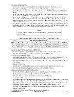
1. Connect the BE1-67N relay as shown in Figure 5-1.
Figure 5-1. Typical Test Connections
2. Adjust the Tap Calibration control fully clockwise.
3. Set the Time Dial at 99.
4. Set the Tap Selector switch in position A.
5. Adjust the Directional, Instantaneous Overcurrent control and Non-Directional, Instantaneous
Overcurrent control fully clockwise.
6. Place the Characteristic Angle switch in the 0
°
position.
7. Set the Polarizing Source Select switch (locator A of Figure 2-2) for dual polarization (both the V
O
and
I
O
switches up).
Summary of Contents for BE1-67N
Page 2: ......
Page 6: ...iv BE1 67N Introduction 9190700990 Rev F This page intentionally left blank...
Page 8: ...vi BE1 67N Introduction 9190700990 Rev F This page intentionally left blank...
Page 10: ...ii BE1 67N General Information 9190700990 Rev F This page intentionally left blank...
Page 18: ...1 8 BE1 67N General Information 9190700990 Rev F This page intentionally left blank...
Page 20: ...ii BE1 67N Controls and Indicators 9190700990 Rev F This page intentionally left blank...
Page 26: ...ii BE1 67N Functional Description 9190700990 Rev F This page intentionally left blank...
Page 34: ...ii BE1 67N Installation 9190700990 Rev F This page intentionally left blank...
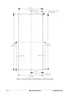
Page 39: ...9190700990 Rev F BE1 67N Installation 4 5 Figure 4 4 Case Dimensions Rear View...
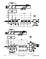
Page 43: ...9190700990 Rev F BE1 67N Installation 4 9 Figure 4 7 Typical Internal Connections...
Page 46: ...4 12 BE1 67N Installation 9190700990 Rev F This page intentionally left blank...
Page 48: ...ii BE1 67N Testing 9190700990 Rev F This page intentionally left blank...
Page 58: ...ii BE1 67N Characteristic Curves 9190700990 Rev F This page intentionally left blank...
Page 72: ...A 14 BE1 67N Characteristic Curves 9190700990 Rev F This page intentionally left blank...
Page 74: ...B 2 BE1 67N Polar Graph Forms 9190700990 Rev F This page intentionally left blank...


