9310200990 Rev G
BE1-79A General Information
1-1
SECTION 1
•
GENERAL INFORMATION
DESCRIPTION
The BE1-79A Reclosing Relay is an economical, microprocessor-based relay that automatically recloses
circuit breakers that have been tripped by protective relays or other devices in power transmission and
distribution systems. The BE1-79A offers true "plug and play" convenience; it can be installed in an
existing GE type S2 case with no wiring changes required. General Electric type ACR11A, ACR11B,
ACR11C, ACR11E, and ACR11F reclosing relays can be directly replaced by the BE1-79A-100 or BE1-
79A-101. The BE1-79A-200 is available in a shorter cradle that fits in a Basler S1 case for new
installations.
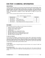
Table 1-1 lists the case style and special features of each version of the BE1-79A.
Table 1-1. BE1-79A Versions and Features
Catalog Number
Options
Cradle Style
BE1-79A-100 None
S2
BE1-79A-101
Power holdup circuit
S2
BE1-79A-200 Mounting
case
included
S1
BE1-79A-201
Power holdup circuit and mounting case included
S1
FEATURES
BE1-79A Multiple Shot Reclosing Relays have the following standard features:
•
Rugged construction in a steel, draw-out case
•
A maximum of four automatic reclosures
•
A maximum of four automatic resets
•
Lockout
function
•
Selectable instantaneous or delayed first reclosure
•
Selectable internal or external instantaneous jumper
•
Selectable normally closed or normally open RS output contact
•
Selectable Relay Fail or Lockout and Relay Fail output contact
•
Selectable contact sensing voltage range
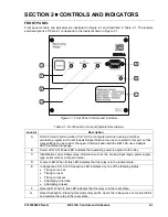
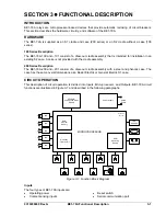
Controls and Indicators
The front panel has indicators to verify relay power and recloser status. A Reset switch is provided to
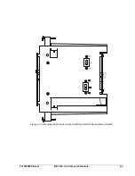
restore the relay to the reset mode by clearing a reclosing sequence or a lockout condition. The left side
of the relay cradle has switches (S1, S2, and S3) to configure the relay for either ACR11A or ACR11B
operation. The right side of the cradle has a switch (S4) to select either an internal or an external jumper
for an instantaneous, first reclose. The right side of the cradle also has a switch (S5) to select either
normally open or normally closed operation of the RS contact.
Communication
All relay settings are read or changed through the serial port located on the front panel. The BE1-79A
uses ASCII protocol.
Power Holdup Circuit
The BE1-79A is available with an optional, internal, power holdup circuit. This circuitry maintains the
output contacts for a minimum of 40 cycles after nominal operating power is removed from relay terminals
5 and 6.
Summary of Contents for BE1-79A
Page 1: ...INSTRUCTION MANUAL FOR RECLOSING RELAY BE1 79A Publication 9310200990 Revision G 02 08...
Page 2: ......
Page 8: ...vi BE1 79A Introduction 9310200990 Rev G This page intentionally left blank...
Page 10: ...ii BE1 79A General Information 9310200990 Rev G This page intentionally left blank...
Page 16: ...ii BE1 79A Controls and Indicators 9310200990 Rev G This page intentionally left blank...
Page 20: ...2 4 BE1 79A Controls and Indicators 9310200990 Rev G This page intentionally left blank...
Page 22: ...ii BE1 79A Functional Description 9310200990 Rev G This page intentionally left blank...
Page 34: ...ii BE1 79A Communication Commands 9310200990 Rev G This page intentionally left blank...
Page 40: ...ii BE1 79A Installation and Configuration 9310200990 Rev G This page intentionally left blank...
Page 52: ...ii BE1 79A Testing 9310200990 Rev G This page intentionally left blank...
Page 58: ...6 6 BE1 79A Testing 9310200990 Rev G This page intentionally left blank...
Page 60: ...ii BE1 79A RS Contact Application 9310200990 Rev G This page intentionally left blank...
Page 66: ...ii BE1 79A Terminal Communication 9310200990 Rev G This page intentionally left blank...


