9310200990 Rev G
BE1-79A Testing
6-5
POWER HOLDUP CIRCUIT TESTING
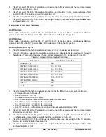
Power holdup circuit testing applies only to BE1-79 relays with part numbers 9310200101 and
9310200201.
Part Numbers 9310200101 and 9310200201
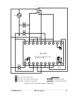
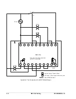
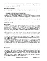
Remove 120 Vac operating power from terminals 5 and 6. Measure the time from when the operating
power is removed until the RS contacts (terminals 9 and 10) close. The time should be 1.3 seconds or
greater.
TROUBLESHOOTING TIPS
The front panel LED indicators will annunciate certain conditions that will inhibit the BE1-79A relay from
providing reclose protection.
Blinking LEDs
This annunciation indicates low or incorrect relay input voltage. Verify proper contact sensing jumper
selection.
All LEDs On
This annunciation indicates an EEPROM error or recent cycling of relay operating power.
Summary of Contents for BE1-79A
Page 1: ...INSTRUCTION MANUAL FOR RECLOSING RELAY BE1 79A Publication 9310200990 Revision G 02 08...
Page 2: ......
Page 8: ...vi BE1 79A Introduction 9310200990 Rev G This page intentionally left blank...
Page 10: ...ii BE1 79A General Information 9310200990 Rev G This page intentionally left blank...
Page 16: ...ii BE1 79A Controls and Indicators 9310200990 Rev G This page intentionally left blank...
Page 20: ...2 4 BE1 79A Controls and Indicators 9310200990 Rev G This page intentionally left blank...
Page 22: ...ii BE1 79A Functional Description 9310200990 Rev G This page intentionally left blank...
Page 34: ...ii BE1 79A Communication Commands 9310200990 Rev G This page intentionally left blank...
Page 40: ...ii BE1 79A Installation and Configuration 9310200990 Rev G This page intentionally left blank...
Page 52: ...ii BE1 79A Testing 9310200990 Rev G This page intentionally left blank...
Page 58: ...6 6 BE1 79A Testing 9310200990 Rev G This page intentionally left blank...
Page 60: ...ii BE1 79A RS Contact Application 9310200990 Rev G This page intentionally left blank...
Page 66: ...ii BE1 79A Terminal Communication 9310200990 Rev G This page intentionally left blank...


