A-4
BE1-79A RS Contact Application
9310200990 Rev G
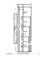
From Table A-1, for mode E settings, an NO RS contact (S5 = NO, mode = E) will be open during BE1-
79A power-off and will be energized and closed when the BE1-79A relay is powered on and in Reset
position. The NO contact will remain closed until the reclose cycle begins. At that time, the NO contact will
continue to remain closed until the RS Apply time is reached. The NO contact will then open and remain
open until the RS contact Remove time is reached. (If relay power is lost during this time, the NO contact
will remain open.)
When the Remove time is reached or the BE1-79A resets, the NO contact will again close and remain
closed until the next reclose cycle begins from the Reset position.
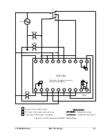
RS CONTACT EXAMPLE FOR TRANSFORMER LTC BLOCKING
SP-79ARS Mode Selection
If using the de-energized mode (mode = D), be aware that the RS contact will revert to the de-energized
state during loss of BE1-79A operating power. Therefore, if power is lost during the reclose cycle, the NO
RS contact (S5 = NC) being held open to block the LTC will change state and remove the LTC blocking
while the relay is without power. If a reliable dc power source to terminals 5 and 6 is available, it will
prevent this from occurring.
If using the Energized mode (mode = E) and the normally open RS contact (S5 = NO), it will revert to the
de-energized state during loss of BE1-79A operating power. If operating power is lost during the reclose
cycle, the NO RS contact being held open to block the LTC will remain open and continue the block. If the
relay power to terminals 5 and 6 is lost at any other time (during breaker maintenance, a common dc
power source may be turned off), the RS contact will change state and block the LTC, which may be
undesirable under these circumstances. Awareness of this condition will enable the user to take the
necessary steps to prevent the condition from occurring.
SP-79ARS Remove Time Selection
The RS contact Remove time, when used for LTC blocking, should be long enough to allow a complete
reclose cycle to occur but shorter than the final closure’s reset time and before lockout time is reached.
This ensures that the RS contact is blocking LTC operation during the reclose sequence but is reset to its
normal condition before the next reclose cycle begins. The LTC will then be functioning normally even
when the breaker has operated to the lockout condition.
RS Contact Example for Blocking Instantaneous Overcurrent Tripping
The BE1-79A has the following settings with switch S5 set for NC:
SP-79A1=0,10
SP-79A2=15,25
SP-79A3=45,55
SP-79A4=0,0
SP-79ALO=60,65
SP-79ARS=D,5,58
SP-ALM=2
With the NC (in de-energized mode) BE1-79A RS contact wired in series with an instantaneous over-
current (50) device trip circuit, it will open or block tripping of a circuit breaker by the 50 element five
seconds after the first trip of the breaker. The BE1-79A is programmed to close the breaker instantly for
its firs close (SP-79A1=0,10). If the breaker trips a second time before 10 seconds have elapsed, the
BE1-79A RS contact will open at the Apply time setting of five seconds and remain open until the
Remove time of 58 seconds from the first trip is reached. This will permit the 50 element to be in service
when the breaker is closed after lockout.
If the breaker successfully closes on any of the three programmed close times of up to 45 seconds from
the first trip and resets, then the Remove time also will be reset. Resetting the Remove time will restore
the RS contact to its original NC position and restore the 50 element tripping for the next fault occurrence
and trip-close sequence of the circuit breaker.
If the 50 element is to remain blocked when the BE1-79A is in lockout, then the RS contact Remove time
should be set for 65 seconds also (SP-79ARS=D,5,65).
Summary of Contents for BE1-79A
Page 1: ...INSTRUCTION MANUAL FOR RECLOSING RELAY BE1 79A Publication 9310200990 Revision G 02 08...
Page 2: ......
Page 8: ...vi BE1 79A Introduction 9310200990 Rev G This page intentionally left blank...
Page 10: ...ii BE1 79A General Information 9310200990 Rev G This page intentionally left blank...
Page 16: ...ii BE1 79A Controls and Indicators 9310200990 Rev G This page intentionally left blank...
Page 20: ...2 4 BE1 79A Controls and Indicators 9310200990 Rev G This page intentionally left blank...
Page 22: ...ii BE1 79A Functional Description 9310200990 Rev G This page intentionally left blank...
Page 34: ...ii BE1 79A Communication Commands 9310200990 Rev G This page intentionally left blank...
Page 40: ...ii BE1 79A Installation and Configuration 9310200990 Rev G This page intentionally left blank...
Page 52: ...ii BE1 79A Testing 9310200990 Rev G This page intentionally left blank...
Page 58: ...6 6 BE1 79A Testing 9310200990 Rev G This page intentionally left blank...
Page 60: ...ii BE1 79A RS Contact Application 9310200990 Rev G This page intentionally left blank...
Page 66: ...ii BE1 79A Terminal Communication 9310200990 Rev G This page intentionally left blank...

