3-2
BE1-79A Functional Description
9310200990 Rev G
Operating Power
Operating power for the internal circuitry is applied to the internal, isolated, switching power supply. The
power supply operates over a range of 120 to 240 Vac or 125 to 250 Vdc with no connection changes or
jumpers required. The operating power input is not polarity sensitive and is not disrupted by variations in
the supply voltage or frequency over the power supply operating range. The power supply generates a 24
Vdc output.
BE1-79A-101 and BE1-79A-201 relays are equipped with holdup circuitry that maintains relay function for
a minimum of 40 cycles after nominal operating power is removed.
Contact Sensing Inputs
The contact sensing inputs are designated V1, V2, V3, V4, and V5. Each input is optically isolated to
electrically insulate the input from external power sources. Each contact sensing input is rated for 48 to
250 Vdc and 120 to 240 Vac at 45 to 65 hertz.
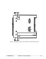
Inputs V1 through V4 can operate at any one of
three jumper-selectable voltage ranges. Table 3-1
lists the nominal operating voltage for each of the
three jumper positions. Each input has a dedicated
jumper that is located on the digital circuit board.
Jumper P3 controls the operating voltage for V1, P4
controls V2, P5 controls V3 and P6 controls V4.
Instructions for placing each jumper in the desired
position are provided in Section 5,
Installation and
Configuration
. Input V5 is dedicated to monitoring
the relay power supply input and is not jumper
selectable.
Table 3-1. Contact Sensing Jumpers
Jumper Position
Nominal Voltage
1
125 Vdc or 120 Vac
2 48
Vdc
3
250 Vdc or 240 Vac
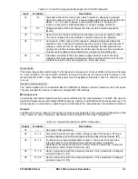
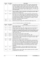
The function of each input depends on the operating configuration of the relay. Tables 3-2 and 3-3
describe the function of each contact sensing input for each relay configuration. The GE nomenclature
used for each input is provided in parenthesis following each description.
Table 3-2. Contact Sensing Inputs Description for ACR11A Operation
Input Terminals
Description
V1
3, 4
Typically connects to a 52a contact, which results in voltage being sensed
when the breaker is closed. If V1 senses voltage within three seconds after the
Reset 1, 2, 3, or 4 timer expires, a reset will be initiated. If the relay is in
lockout, a reset will be initiated anytime V1 senses voltage. (E Reset)
V2
7, 8
Connects to a 52b contact, which results in voltage being sensed when the
breaker is open. This input is typically used to provide an anti-pump feature. If
voltage is removed from V2 during a reclose attempt, the anti-pump feature
will prevent a further reclose attempt until the next reclose set time is reached.
This prevents multiple reclose attempts for a single reclose setting. (Z)
V3
11, 12
Used to monitor the 52b contact while the relay is in a reset condition. When
V3 senses voltage, the relay initiates a reclose sequence. (E Operate)
V4
—
Not used in this application.
V5
5, 6
Internally connected to the relay power supply terminal. A loss of sensing
voltage at this input causes all necessary data to be stored in memory and all
contacts to return to their de-energized or “in-the-box” state.
NOTE
In certain applications where 240 Vac control voltage is used, control circuit
feedback can occur through system inductive coupling. This feedback can result
in erroneous signals, causing relay operation. If there is potential for control
circuit feedback, the jumper-selectable voltage range should be changed from
the 48 Vdc, factory-default setting to a higher value. Selections are listed in Table
3-1.
Summary of Contents for BE1-79A
Page 1: ...INSTRUCTION MANUAL FOR RECLOSING RELAY BE1 79A Publication 9310200990 Revision G 02 08...
Page 2: ......
Page 8: ...vi BE1 79A Introduction 9310200990 Rev G This page intentionally left blank...
Page 10: ...ii BE1 79A General Information 9310200990 Rev G This page intentionally left blank...
Page 16: ...ii BE1 79A Controls and Indicators 9310200990 Rev G This page intentionally left blank...
Page 20: ...2 4 BE1 79A Controls and Indicators 9310200990 Rev G This page intentionally left blank...
Page 22: ...ii BE1 79A Functional Description 9310200990 Rev G This page intentionally left blank...
Page 34: ...ii BE1 79A Communication Commands 9310200990 Rev G This page intentionally left blank...
Page 40: ...ii BE1 79A Installation and Configuration 9310200990 Rev G This page intentionally left blank...
Page 52: ...ii BE1 79A Testing 9310200990 Rev G This page intentionally left blank...
Page 58: ...6 6 BE1 79A Testing 9310200990 Rev G This page intentionally left blank...
Page 60: ...ii BE1 79A RS Contact Application 9310200990 Rev G This page intentionally left blank...
Page 66: ...ii BE1 79A Terminal Communication 9310200990 Rev G This page intentionally left blank...


