2-4
BE1-79S Functional Description
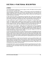
If a breaker trip occurs before the reset interval has expired, the RESET signal is not generated, the internal
lockout relay is energized (if not previously energized by a close command), and the relay will not attempt
to close the breaker or to reset its circuits. When this occurs, resetting of the relay requires closing the
controlled breaker by other means and its remaining closed for the duration of the reset interval.
VOLTAGE MONITOR (Option 2-D or 2-S)
This circuitry monitors a single-phase each of line and bus voltages and inhibits operation of the reclose
logic unless specific voltage conditions are met. Selector switches and adjustment controls allow tailoring
operation of the relay to a wide range of line/bus closing conditions.
Circuit board mounted switches provide selection of any combination of four permissible closing conditions:
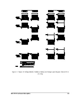
LIVE-LINE/LIVE-BUS, DEAD-LINE/LIVE-BUS, LIVE-LINE/DEAD-BUS, AND DEAD-LINE/DEAD-BUS (see
Figure 2-2). Four front panel controls provide independent selection of the live and dead voltage levels for
the line and bus inputs over the range of 10 to 135 volts. This scheme establishes precise voltage conditions
under which reclosing can occur. Non-selection of specific closing conditions prevents closing from occurring
during these conditions.
As an example, the reclosing relay may be programmed for LIVE-LINE/LIVE-BUS DEAD-LINE/LIVE-BUS
closing, with the individual controls set for: LIVE-LINE, above 100 volts; DEAD-LINE, below 40 volts; and
LIVE-BUS, above 35 volts (Figure 2-3). In this case, reclosing would be permitted only when the line and
bus voltage conditions satisfy the front panel settings. If these conditions are not met, the voltage monitor
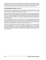
circuit generates an INHIBIT signal to disable the automatic reclose enable logic.
Circuit board-mounted MODE switches allow selection of either a "normal
”
mode or an overvoltage limit (OV)
mode (
“
normal" mode denotes non-operation of the OV mode). MODE switch no. 1 (for the live-bus
condition) and MODE switch no. 2 (for the live-line condition) allow independent selection of an adjustable
overvoltage limit (OV) level that defines a live voltage band for permissible relay closing (see Figure 2-2).
In this mode, live-line or live-bus closing will be permitted if the appropriate monitored voltage(s) is within
the permissible band.
Summary of Contents for BE1-79S
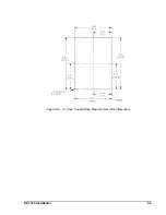
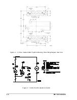
Page 26: ...BE1 79S Installation 4 5 Figure 4 5 S1 Case Panel Drilling Diagram Semi Flush Mounting...
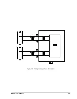
Page 28: ...BE1 79S Installation 4 7 Figure 4 8 Voltage Sensing Circuit Connections...
Page 29: ...4 8 BE1 79S Installation Figure 4 9 RI RC and 52b Sensing Circuit Connections...
Page 30: ...BE1 79S Installation 4 9 Figure 4 10 Internal Connection Diagram With Power Supply Status...


