2-6
BE1-79S Functional Description
NOTE
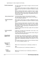
For proper operation of the voltage monitor logic, the "live" controls, when not used, must
be adjusted above the "dead" control leads, but below 80 Vac. Unused "dead" controls
must be adjusted fully CCW, then backed off one turn.
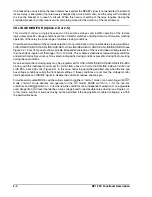
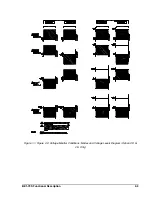
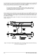
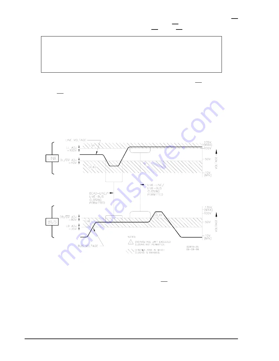
As shown in Figure 2-3, closing will not be permitted if the monitored bus voltage is above the selected OV
setting of 80 volts or below the "live" setting of 35 volts. Adjustments of the OV limits for the live-line and live-
bus are provided by the dual-function front panel controls, DL/ OV and DB/OV.
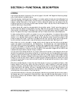
When the situation occurs in which both a live zone and a dead zone are elected, and OV is selected for the
live zone, the dead zone will occupy the area immediately below the live zone established by the LL or LB
control (see the OV MODE column of Figure 2-2, using the combined live-line/dead-bus and dead-line/live-
bus conditions as examples).
Figure 2-4 provides further examples of the selection of line and bus live/dead zones using the selection
diagram of Figure 2-2.
Figure 2-3. Example of Optional Voltage Monitor Live-Line/Live-Bus and Dead-Line/Live-Bus Reclosing
with Live-Bus Overvoltage Limit (OV)
Summary of Contents for BE1-79S
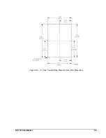
Page 26: ...BE1 79S Installation 4 5 Figure 4 5 S1 Case Panel Drilling Diagram Semi Flush Mounting...
Page 28: ...BE1 79S Installation 4 7 Figure 4 8 Voltage Sensing Circuit Connections...
Page 29: ...4 8 BE1 79S Installation Figure 4 9 RI RC and 52b Sensing Circuit Connections...
Page 30: ...BE1 79S Installation 4 9 Figure 4 10 Internal Connection Diagram With Power Supply Status...


