BE1-79S Operational Test
5-1
NOTE
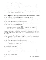
If the optional voltage logic (Option 2-S, D) is installed in the relay, perform steps 2
through 22. If not, proceed to the note which follows step 22.
NOTE
The front panel LL, LB, DL/OV and DB/OV controls are multiturn controls requiring a
screwdriver for adjustment.
NOTE
Steps 6 through 9 verify operation of maximum and minimum voltage monitor settings
for live-line and live-bus.
SECTION 5 • OPERATIONAL TEST
GENERAL
The procedures in this section are for use in testing the relay and for selecting the optional (Option 2-S and
2-D) line and bus voltage monitoring levels.
If a relay fails an operational test, or if the optional voltage monitor reclose enable level selection is faulty,
and factory repair is desired, contact the Customer Service Department of the Power Systems Group, Basler
Electric, for a return authorization number prior to shipping.
RECLOSING RELAY OPERATIONAL TEST
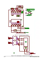
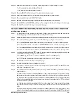
Step 1. Connect the relay as shown in Figures 5-1 and 5-2. If equipped with Power Supply Status Output
(Option 2-F), and with the unit in a powered-up condition, verify that the power supply status output
contact is energized open (terminals 11 and 16). Remove input power and verify that the status
output contact closes. Restore input power.
Step 2. To gain access to the voltage monitor board CONDITION and MODE switches, remove the
connecting plugs and remove the cradle assembly from the relay.
Step 3. Ensure that all CONDITION and MODE switches on the voltage monitor board are set to normal (up)
or off (up) (see Figure 3-2).
Step 4. Re-install the cradle in the relay and replace plugs.
Step 5. Adjust the LL and LB controls fully CW, and the LB/OV and DB/OV controls fully CCW.
Step 6. Adjust the T1 (bus) and T2 (line) output voltages to 135 Vac.
Step 7. Adjust the LL and LB controls until the LL and LB indicators light. Both adjustments should require
only a few turns from the maximum (fully CW) position.
Step 8. Adjust the T1 (bus) and T2 (line) output voltages to 10 Vac, extinguishing both indicators.
Step 9. Adjust the LL and LB controls CCW until the LL and LB indicators light. Both adjustments should
be near their minimum turn limits.
Summary of Contents for BE1-79S
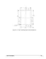
Page 26: ...BE1 79S Installation 4 5 Figure 4 5 S1 Case Panel Drilling Diagram Semi Flush Mounting...
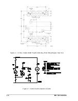
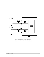
Page 28: ...BE1 79S Installation 4 7 Figure 4 8 Voltage Sensing Circuit Connections...
Page 29: ...4 8 BE1 79S Installation Figure 4 9 RI RC and 52b Sensing Circuit Connections...
Page 30: ...BE1 79S Installation 4 9 Figure 4 10 Internal Connection Diagram With Power Supply Status...


