5-
5
BE1-79S Operational Test
NOTE
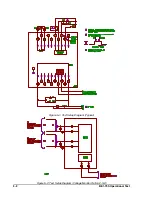
Input to timer in STEP 43 is reverse of that shown in Figure 5-1. Voltage goes low on trip
and returns to high when reclose signal terminates.
NOTE
If the optional voltage monitor (Option 2-S, D) is installed in the relay, perform the
remainder of the test. If not, the test is ended here.
NOTE
If equipped with Reset Timer D, omit steps 56 through 60.
be cleared by an automatic reclose signal.
Step 43. Observe RESET LED goes out and LOCKOUT LED lights and remains lit. If relay is provided with
Option 3-0 (continuous reclose signal) the timer is started and not stopped. If relay is provided with
Option 3-2, the timer will indicate between 2 and 3 seconds. If relay is provided with Option 3-3,
the timer will indicate between 5 and 6 seconds.
Step 44. Release switch S2, remove jumper installed in STEP 42. Press and release switch S1 to simulate
closing the breaker by other means.
Step 45. Observe after 60 seconds LOCKOUT LED goes out and RESET LED lights.
Step 46. Press and release S2 and immediately press S3 to simulate a breaker trip followed by an RC
signal.
Step 47. Observe RESET LED goes out. No automatic reclosure occurs.
Step 48. Press and release switch S1 to simulate closing the breaker by other means.
Step 49. Observe after 60 seconds RESET LED lights.
The following steps simulate a breaker trip with a live-line overvoltage condition such that the line voltage
is higher than the OV setting established in STEP 21. The voltage monitor timer that prevents reclosing is
then checked.
Step 50. Ensure K1 is energized by pressing and releasing S1.
Step 51. Adjust the T2 output voltage to 120 Vac, so that the live-line voltage is above the OV level of 100
Vac.
Step 52. Depress and release S2 to simulate a breaker trip.
Step 53. Observe RESET LED goes out. No automatic reclosure occurs.
Step 54. When the timer indicates 'X' seconds, rapidly adjust the T2 output voltage to 70 Vac.
X = 80 seconds for units with Reset Timer B.
X = 10 seconds for units with Reset Timer C.
(Don't do test for units with Reset Timer D.)
Step 55. Observe K1 is energized after two seconds.
Step 56. Repeat steps 50 through 53.
Summary of Contents for BE1-79S
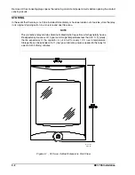
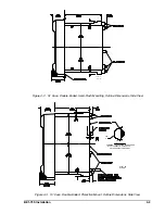
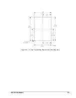
Page 26: ...BE1 79S Installation 4 5 Figure 4 5 S1 Case Panel Drilling Diagram Semi Flush Mounting...
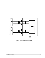
Page 28: ...BE1 79S Installation 4 7 Figure 4 8 Voltage Sensing Circuit Connections...
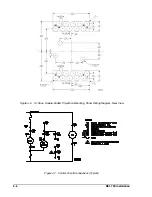
Page 29: ...4 8 BE1 79S Installation Figure 4 9 RI RC and 52b Sensing Circuit Connections...
Page 30: ...BE1 79S Installation 4 9 Figure 4 10 Internal Connection Diagram With Power Supply Status...

