1-2
BE1-79S General Information
The relay assembly is mounted in a drawout cradle and enclosed in a standard, utility style, semi-flush case.
Test points and circuit components are accessible by removal of the individual printed circuit boards from
the relay cradle and using an extender board (Basler part number 9 1129 30 101) to test or troubleshoot.
An available test plug (Basler part number 10095) permits the relay to be tested in place without disturbing
external control circuit wiring.
MODEL AND STYLE NUMBER
The electrical characteristics and optional features included in a particular style BE1-79S Reclosing Relay
are defined by a combination of letters and numbers that make up its style number. The model number, and
style number, describing the options included in the specific device, appear on the front panel, drawout
cradle, and inside the case assembly. Upon receipt of a reclosing relay, be sure to check relay style number
against the requistion and packing list to see that they agree.
Style Number Example
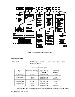
The Style Number Identification Chart (Figure 1-1) defines the electrical characteristics and operational
features included in BE1-79S relays. For example, if the Style Number were
1lN A4C B4S0F
, the device
would have the following:
(B) Single-shot reclosing with reclose initiate and reclose cancel.
(1)
Lockout and reset circuits.
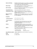
(A4) Reclose time delay continuously variable over the range of 5 to 60 seconds.
(C) Internal relay operating power to be obtained from an external 125 Vdc or 100/120 Vac, 50/60
Hz source.
(B) A reset timer that is continuously adjustable over the range of 5 to 60 seconds, together with a
95 second limit for the voltage monitor to accept line and bus conditions.
(4)
Non-isolated contact sensing input is supplied.
(S) Line and bus voltage monitor is supplied.
(0)
The reclose signal is continuous until controlled breaker is closed.
(F) Semi-flush mounting.
Summary of Contents for BE1-79S
Page 26: ...BE1 79S Installation 4 5 Figure 4 5 S1 Case Panel Drilling Diagram Semi Flush Mounting...
Page 28: ...BE1 79S Installation 4 7 Figure 4 8 Voltage Sensing Circuit Connections...
Page 29: ...4 8 BE1 79S Installation Figure 4 9 RI RC and 52b Sensing Circuit Connections...
Page 30: ...BE1 79S Installation 4 9 Figure 4 10 Internal Connection Diagram With Power Supply Status...


