Summary of Contents for BE1-81
Page 1: ... 05647 6 10 07 14 6 70 4 4 37 0 4 1 2WDNKECVKQP 4GXKUKQP ...
Page 7: ...BE1 81 General Information 1 2 Figure 1 1 Inverse Time Curves 50 Hertz Option ...
Page 8: ...BE1 81 General Information 1 3 Figure 1 2 Inverse Time Curves 60 Hertz Option ...
Page 13: ...BE1 81 Controls And Indicators 2 2 Figure 2 1 Location Of Controls And Indicators Option E1 ...
Page 14: ...BE1 81 Controls And Indicators 2 3 Figure 2 2 Location Of Controls And Indicators Option D1 ...
Page 15: ...BE1 81 Controls And Indicators 2 4 Figure 2 3 Location Of Assemblies ...
Page 22: ...BE1 81 Installation 4 3 Figure 4 3 S1 Case Single Ended Semi Flush Mounting Side View ...
Page 25: ...BE1 81 Installation 4 6 Figure 4 6 S1 Case Single Ended Projection Mounting Rear View ...
Page 26: ...BE1 81 Installation 4 7 Figure 4 7 S1 Case Single Ended Projection Mounting Side View ...
Page 27: ...BE1 81 Installation 4 8 Figure 4 8 S1 Case Double Ended Semi Flush Mounting Side View ...
Page 30: ...BE1 81 Installation 4 11 Figure 4 11 S1 Case Double Ended Projection Mounting Rear View ...
Page 31: ...BE1 81 Installation 4 12 Figure 4 12 S1 Case Double Ended Projection Mounting Side View ...
Page 33: ...BE1 81 Installation 4 14 Figure 4 14 DC Control Connections ...
Page 34: ...BE1 81 Installation 4 15 Figure 4 15 Internal Connections Style Number T E 1 A0S5 ...
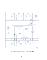
Page 35: ...BE1 81 Installation 4 16 Figure 4 16 Internal Connections Style Number T E 1C A2S5 ...


