5-1
SECTION 5
TESTING
GENERAL
The test setups and procedures contained in this section are suggested for use in verifying or setting the
desired pickup frequency threshold, as well as the time delay parameters, for both the definite and
inverse time delay style of relay. Accuracy of the measurements in these procedures is dependent upon
the stability of the test frequency sources, and the resolution of the frequency and time measuring test
equipment. Functional tests performed with test equipment with an overall accuracy of less than the
accuracy of the relay may be useful to the extent that they verify relay operation and approximate relay
characteristics. However, tests performed under these conditions will not verify or produce calibrations
any better than the test equipment accuracy; as a result, tolerances may be outside of those specified.
TEST SETUP
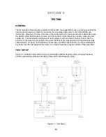
Figure 5-1 illustrates a test setup using a commercially available frequency test set having frequency
and time generating accuracies exceeding those of the underfrequency relay.
Figure 5-1. Test Setup
Summary of Contents for BE1-81
Page 1: ... 05647 6 10 07 14 6 70 4 4 37 0 4 1 2WDNKECVKQP 4GXKUKQP ...
Page 7: ...BE1 81 General Information 1 2 Figure 1 1 Inverse Time Curves 50 Hertz Option ...
Page 8: ...BE1 81 General Information 1 3 Figure 1 2 Inverse Time Curves 60 Hertz Option ...
Page 13: ...BE1 81 Controls And Indicators 2 2 Figure 2 1 Location Of Controls And Indicators Option E1 ...
Page 14: ...BE1 81 Controls And Indicators 2 3 Figure 2 2 Location Of Controls And Indicators Option D1 ...
Page 15: ...BE1 81 Controls And Indicators 2 4 Figure 2 3 Location Of Assemblies ...
Page 22: ...BE1 81 Installation 4 3 Figure 4 3 S1 Case Single Ended Semi Flush Mounting Side View ...
Page 25: ...BE1 81 Installation 4 6 Figure 4 6 S1 Case Single Ended Projection Mounting Rear View ...
Page 26: ...BE1 81 Installation 4 7 Figure 4 7 S1 Case Single Ended Projection Mounting Side View ...
Page 27: ...BE1 81 Installation 4 8 Figure 4 8 S1 Case Double Ended Semi Flush Mounting Side View ...
Page 30: ...BE1 81 Installation 4 11 Figure 4 11 S1 Case Double Ended Projection Mounting Rear View ...
Page 31: ...BE1 81 Installation 4 12 Figure 4 12 S1 Case Double Ended Projection Mounting Side View ...
Page 33: ...BE1 81 Installation 4 14 Figure 4 14 DC Control Connections ...
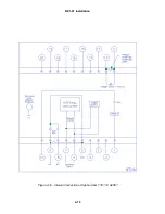
Page 34: ...BE1 81 Installation 4 15 Figure 4 15 Internal Connections Style Number T E 1 A0S5 ...
Page 35: ...BE1 81 Installation 4 16 Figure 4 16 Internal Connections Style Number T E 1C A2S5 ...


