7-1
5'%6+10
/#07#.%*#0)'+0(14/#6+10
57//#4;#0&%41554'('4'0%')7+&'
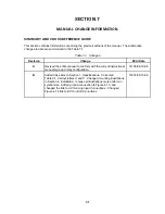
This section contains information concerning the previous editions of the manual. The substantive
changes to date are summarized in the Table 7-1.
Table 7-1. Changes
Revision
Change
ECA/Date
A
Revised the entire manual to conform with the current instructional
manual style and relay configuration.
14138/04-18-96
B
Added Case Size to Section 1,
Specifications. Corrected
Table 2-1, Callout letters
A and F. Changed mounting illustrations
in Section 4,
Installation, to make all illustrations more uniform in
symbol size. Added ground connection to Figure 4-13, and
changed the title to
AC Sensing Input Connections. Changed
Figure 4-14 title to
DC Control Connections.
15574/05-15-96
Summary of Contents for BE1-81
Page 1: ... 05647 6 10 07 14 6 70 4 4 37 0 4 1 2WDNKECVKQP 4GXKUKQP ...
Page 7: ...BE1 81 General Information 1 2 Figure 1 1 Inverse Time Curves 50 Hertz Option ...
Page 8: ...BE1 81 General Information 1 3 Figure 1 2 Inverse Time Curves 60 Hertz Option ...
Page 13: ...BE1 81 Controls And Indicators 2 2 Figure 2 1 Location Of Controls And Indicators Option E1 ...
Page 14: ...BE1 81 Controls And Indicators 2 3 Figure 2 2 Location Of Controls And Indicators Option D1 ...
Page 15: ...BE1 81 Controls And Indicators 2 4 Figure 2 3 Location Of Assemblies ...
Page 22: ...BE1 81 Installation 4 3 Figure 4 3 S1 Case Single Ended Semi Flush Mounting Side View ...
Page 25: ...BE1 81 Installation 4 6 Figure 4 6 S1 Case Single Ended Projection Mounting Rear View ...
Page 26: ...BE1 81 Installation 4 7 Figure 4 7 S1 Case Single Ended Projection Mounting Side View ...
Page 27: ...BE1 81 Installation 4 8 Figure 4 8 S1 Case Double Ended Semi Flush Mounting Side View ...
Page 30: ...BE1 81 Installation 4 11 Figure 4 11 S1 Case Double Ended Projection Mounting Rear View ...
Page 31: ...BE1 81 Installation 4 12 Figure 4 12 S1 Case Double Ended Projection Mounting Side View ...
Page 33: ...BE1 81 Installation 4 14 Figure 4 14 DC Control Connections ...
Page 34: ...BE1 81 Installation 4 15 Figure 4 15 Internal Connections Style Number T E 1 A0S5 ...
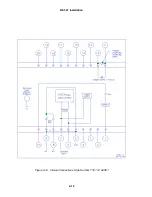
Page 35: ...BE1 81 Installation 4 16 Figure 4 16 Internal Connections Style Number T E 1C A2S5 ...


