5-12
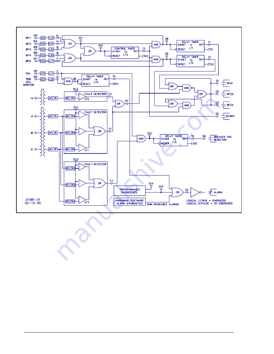
BE1-BPR BESTlogic
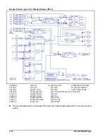
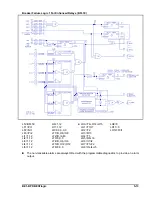
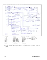
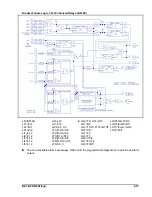
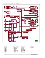
Breaker Failure Logic 3 For Standard Relays (BFL3)
LN=BFL3
LF1=PI,1
LF2=NI,1
LF3=PI,2
LI1=4,12
LI2=4,12
LI3=4,12
LI4=4,12
LI5=4,12
LI6=4,12
U
LI7=4,12
LR=0,0,0,0,0
LT1=D,O8,/O8
LT2=D,O9,/O9
LT3=O10,/O10
LT4=D,O6,/O6
LT5=D,O12,/O12
LT6=0,0,0
LOA=T4+O15
LO1=O3
LO2=O3
LO3=T1O7+F1T2+O1O7
LO4=T5
LO5=T3
LO6=/I1/I2
LO7=F1+F2
LO8=T3O11
LO9=T3I6+T3I7+T3O9
O10=I6+I7+O9+O11
LO11=I3+I4+I5+O8
LO12=F3I1
U
U
The non-maskable alarms are always ORed with the programmable diagnostics to provide an alarm
output.
Summary of Contents for BE1-BPR
Page 31: ...BE1 BPR Application 2 17...
Page 42: ...3 4 BE1 BPR Human Machine Interface Figure 3 4 BE1 BPR Relay Vertical Mount Front View...
Page 43: ...BE1 BPR Human Machine Interface 3 5 Figure 3 5 BE1 BPR Relay Vertical Mount Rear View...
Page 49: ...4 6 BE1 BPR Functional Description Figure 4 2 Enhanced BE1 BPR Menu Display Screens...
Page 50: ...BE1 BPR Functional Description 4 7 Figure 4 3 Standard BE1 BPR Menu Display Screens...
Page 94: ...5 4 BE1 BPR BESTlogic Figure 5 1 BESTlogic Function Blocks...
Page 121: ...BE1 BPR Installation 7 3 Figure 7 3 Overall Dimensions Vertical Mount...
Page 122: ...7 4 BE1 BPR Installation Figure 7 4 Overall Dimensions Side View Vertical Mount...
Page 123: ...BE1 BPR Installation 7 5 Figure 7 5 Panel Drilling Diagram Vertical Mount...

