BE1-BPR Communications
6-3
CREATING SETTINGS FILES
A settings file is useful because one of the standard logic schemes can be modified to suit an application and
then uploaded to several relays. The SHOWSET command allows relay settings to be read, edited, and then
uploaded to BE1-BPR relays.
SHOWSET
Relay settings report
HMI Menu Branch: N/A
Comments
This command returns a report of relay settings and logic equations. SHOWSET can be
used at the end of a programming session to make a record of relay settings. If saved to a
file, the record can be used to setup another relay with the same protection scheme by
sending the data to the other relay.
SHOWSET Command
Purpose:
Returns a report of relay settings and logic equations.
Syntax:
SHOWSET
Comments:
No access area password is required for reporting functions.
SHOWSET Command Example
Obtain a report of the current relay settings.
SHOWSET
PW1=AREA1PW,B; PW2=AREA2PW,B; PW3=AREA3PW,B; PW4=AREA4PW,B
LN=USER
LF1=PI,1; LF2=NI,1; LF3=PI,2
LI1=4,12; LI2=4,12; LI3=4,12; LI4=4,12; LI5=4,12
LI6=4,12; LI7=4,12
LR=0,0,0,0,0
LT1=D,O8,/O8; LT2=D,O9,/O9; LT3=C,O10,/O10; LT4=D,O6,/O6; LT5=D,O12,/O12
LT6=0,0,0
LOA=T4+O15
LO1=O3
LO2=O3
LO3=T1O7+F1T2+O1O7
LO4=T5
LO5=T3
LO6=/I1/I2
LO7=F1+F2
LO8=T3O11
LO9=T3I6+T3I7
LO10=I6+I7+O11
LO11=I3+I4+I5
LO12=F3I1
LOGIC=USER
FREQ=60
ID=0
PU1=1.00; PU2=1.00; PU3=1.00,10
TD1= 20m; TD2= 20m; TD3= 20m; TD4= 20m; TD5= 20m
TD6= 20m
TD791= 111m; TD792= 111m; TD793= 111m; TD79R= 111m; TD79F= 111m
TD79M= 111m
CTP=1; CTN=1; CTI=5
PHOLD=11111
SNAME=5,SUBSTATION_1
PCLK=M,24
PDISPLAY=0,0
COM0=96008N1,A0,E0,H0,P0,X0
COM1=96008N1,A0,E0,H0,P0,X0
PTARGET=0011111,11110
TRIGGER=O5
PTLOG1=0,L,0m; PTLOG2=0,H,11m; PTLOG3=0,L,11m; PTLOG4=0,H,12m; PTLOG5=0,L,13m
PTLOG6=0,H,14m
PDIAG=00000000,00000000
BKRCON=0.000E+00,0,0
BKROPS=,I1
BKRRES=0,0,0.000E+00
The following procedure describes how relay settings can be read, modified, saved to a file, and uploaded
to BE1-BPR relays. Any commercially available communications software may be used. Instructions for
configuring Windows 95
®
HyperTerminal and Windows
®
Terminal are provided in Appendix A,
Terminal
Emulation.
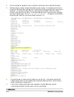
1.
Obtain password access to area one and use the SHOWSET command to obtain a report of all
relay settings. Getting password access to area one before using the SHOWSET command will
ensure that all passwords are displayed in the settings report. If password access is not obtained,
passwords will be displayed as asterisks (********).
Summary of Contents for BE1-BPR
Page 31: ...BE1 BPR Application 2 17...
Page 42: ...3 4 BE1 BPR Human Machine Interface Figure 3 4 BE1 BPR Relay Vertical Mount Front View...
Page 43: ...BE1 BPR Human Machine Interface 3 5 Figure 3 5 BE1 BPR Relay Vertical Mount Rear View...
Page 49: ...4 6 BE1 BPR Functional Description Figure 4 2 Enhanced BE1 BPR Menu Display Screens...
Page 50: ...BE1 BPR Functional Description 4 7 Figure 4 3 Standard BE1 BPR Menu Display Screens...
Page 94: ...5 4 BE1 BPR BESTlogic Figure 5 1 BESTlogic Function Blocks...
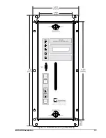
Page 121: ...BE1 BPR Installation 7 3 Figure 7 3 Overall Dimensions Vertical Mount...
Page 122: ...7 4 BE1 BPR Installation Figure 7 4 Overall Dimensions Side View Vertical Mount...
Page 123: ...BE1 BPR Installation 7 5 Figure 7 5 Panel Drilling Diagram Vertical Mount...

