6-4
BE1-BPR Communications
2.
Once the settings are displayed, copy the settings to a text editor such as Microsoft
®
Notepad
®
.
3.
Edit the settings by making changes and deletions where required. You should ensure that each
command is terminated with a carriage return or semicolon and that line length does not exceed 40
characters. An example of settings that were read using the SHOWSET command and then
copied to a text editor is shown below. Text and settings that must be removed prior to uploading
are shown shaded in gray. The
PRESS ANY KEY TO CONTINUE...
message can be avoided by
setting the page mode of your terminal emulation software to “0".
PW1=AREA1PW,B; PW2=AREA2PW,B; PW3=AREA3PW,B; PW4=AREA4PW,B
LN=USER
LF1=PI,1; LF2=NI,1; LF3=PI,2
LI1=4,12; LI2=4,12; LI3=4,12; LI4=4,12; LI5=4,12
LI6=4,12; LI7=4,12
LR=0,0,0,0,0
LT1=D,O8,/O8; LT2=D,O9,/O9; LT3=C,O10,/O10; LT4=D,O6,/O6;
LT5=D,O12,/O12
LT6=0,0,0
LOA=T4+O15
LO1=O3
LO2=O3
LO3=T1O7+F1T2+O1O7
LO4=T5
LO5=T3
LO6=/I1/I2
LO7=F1+F2
LO8=T3O11
LO9=T3I6+T3I7
LO10=I6+I7+O11
LO11=I3+I4+I5
LO12=F3I1
LOGIC=USER
FREQ=60
PRESS ANY KEY TO CONTINUE ...
ID=0
PU1=1.00; PU2=1.00; PU3=1.00,10
TD1= 20m; TD2= 20m; TD3= 20m; TD4= 20m; TD5= 20m
TD6= 20m
TD791= 111m; TD792= 111m; TD793= 111m; TD79R= 111m; TD79F=
111m
TD79M= 111m
CTP=1; CTN=1; CTI=5
PHOLD=11111
SNAME=5,SUBSTATION_1
PCLK=M,24
PDISPLAY=0,0
COM0=96008N1,A0,E0,H0,P0,X0
COM1=96008N1,A0,E0,H0,P0,X0
PTARGET=0011111,11110
TRIGGER=O5
PTLOG1=0,L,0m; PTLOG2=0,H,11m; PTLOG3=0,L,11m; PTLOG4=0,H,12m;
PTLOG5=0,L,13m
PTLOG6=0,H,14m
PDIAG=00000000,00000000
BKRCON=0.000E+00,0,0
BKROPS=,I1
BKRRES=0,0,0.000E+00
>
4.
Once all changes are made, save the settings as a text file (.txt). It is recommended that the
settings saving process can be automated by ending the settings list with the command string
SAVE;Y followed by a carriage return.
5.
The text file containing the settings can be uploaded to any BE1-BPR relay using the
communications software that was used to view the relay settings.
COMMANDS
Summary of Contents for BE1-BPR
Page 31: ...BE1 BPR Application 2 17...
Page 42: ...3 4 BE1 BPR Human Machine Interface Figure 3 4 BE1 BPR Relay Vertical Mount Front View...
Page 43: ...BE1 BPR Human Machine Interface 3 5 Figure 3 5 BE1 BPR Relay Vertical Mount Rear View...
Page 49: ...4 6 BE1 BPR Functional Description Figure 4 2 Enhanced BE1 BPR Menu Display Screens...
Page 50: ...BE1 BPR Functional Description 4 7 Figure 4 3 Standard BE1 BPR Menu Display Screens...
Page 94: ...5 4 BE1 BPR BESTlogic Figure 5 1 BESTlogic Function Blocks...
Page 121: ...BE1 BPR Installation 7 3 Figure 7 3 Overall Dimensions Vertical Mount...
Page 122: ...7 4 BE1 BPR Installation Figure 7 4 Overall Dimensions Side View Vertical Mount...
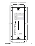
Page 123: ...BE1 BPR Installation 7 5 Figure 7 5 Panel Drilling Diagram Vertical Mount...


