BE1-BPR Communications
6-9
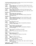
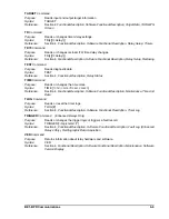
TARGET Command
Purpose:
Reads input and output target information
Syntax:
TARGET
Reference:
Section 4,
Functional Description, Software Functional Description, Target Data, TARGETS
Screen
TD Command
Purpose:
Reads or changes timer delay settings.
Syntax:
TD[x][=<delay>]]
Reference:
Section 4,
Functional Description, Software Functional Description, Relay Setup, Timers
TD79 Command
Purpose:
Reads or changes recloser (79) time delay changes.
Syntax:
TD[x][=<delay>]]
Reference:
Section 4,
Functional Description, Software Functional Description, Relay Setup, Reclosing
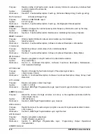
TEST Command
Purpose:
Reads diagnostic data.
Syntax:
TEST
Reference:
Section 4,
Functional Description, Relay Status
TIME Command
Purpose:
Reads or changes the time clock.
Syntax:
TIME [=<hr>:<mn><f><sc>.<msc>]
Reference:
Section 4,
Functional Description, Software Functional Description, Maintenance, Time And
Date
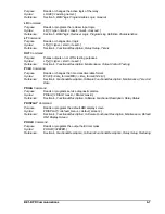
TLOG Command
Purpose:
Reads or reset the timer logs.
Syntax:
TLOG[#]
Reference:
Section 4,
Functional Description, Software Functional Description, Timer Log
TRIGGER Command
(Enhanced Relays Only)
Purpose:
Reads or changes the trigger logic or triggers a fault record.
Syntax:
TRIGGER[=<logic term>/Y]
Reference:
Section 4,
Functional Description, Software Functional Description, Fault Log (Enhanced
Relays Only), Oscillographic Data Acquisition
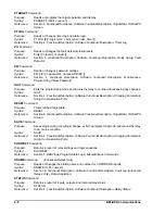
VER Command
Purpose:
Returns information about relay hardware and software.
Syntax:
VER
Reference:
Section 4,
Functional Description, Software Functional Description, Maintenance, Software
Version Display
Summary of Contents for BE1-BPR
Page 31: ...BE1 BPR Application 2 17...
Page 42: ...3 4 BE1 BPR Human Machine Interface Figure 3 4 BE1 BPR Relay Vertical Mount Front View...
Page 43: ...BE1 BPR Human Machine Interface 3 5 Figure 3 5 BE1 BPR Relay Vertical Mount Rear View...
Page 49: ...4 6 BE1 BPR Functional Description Figure 4 2 Enhanced BE1 BPR Menu Display Screens...
Page 50: ...BE1 BPR Functional Description 4 7 Figure 4 3 Standard BE1 BPR Menu Display Screens...
Page 94: ...5 4 BE1 BPR BESTlogic Figure 5 1 BESTlogic Function Blocks...
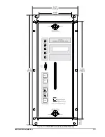
Page 121: ...BE1 BPR Installation 7 3 Figure 7 3 Overall Dimensions Vertical Mount...
Page 122: ...7 4 BE1 BPR Installation Figure 7 4 Overall Dimensions Side View Vertical Mount...
Page 123: ...BE1 BPR Installation 7 5 Figure 7 5 Panel Drilling Diagram Vertical Mount...

