7-6
BE1-BPR Installation
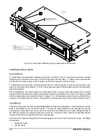
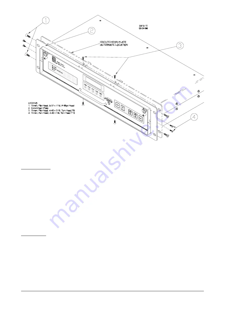
Figure 7-6. Escutcheon Plate Mounting (Vertical Mount Not Shown)
Installing Escutcheon Plates
Horizontal Mount
To install the escutcheon plate kit (Basler part number, 9 2720 13 100) you must first remove the mounting
flanges by removing the four screws (1) from the relay (two from each side). To allow the escutcheon plate
to slide onto the relay, remove the four screws (4) from the relay (two from each side).
To install the escutcheon plate in the standard location, it is also necessary to remove four screws (3), two
each from the relay top and bottom. Position the escutcheon plate at the standard location and reinstall the
attaching hardware.
When installing the escutcheon plate at the alternate location (requires less space behind the mounting
panel), position the escutcheon plate in the alternate location and install the four screws (3) that are provided
with the optional escutcheon plate kit. Refer to Figure 7-7 for the alternate location side view. Reinstall four
screws (4). Reinstall the four screws (1) through the escutcheon plate into the relay at the alternate location.
Vertical Mount
Vertical mount relays come with a standard adjustable escutcheon/mounting plate. The escutcheon/mounting
plate is pre-installed to the 9.452 inch depth. This can be easily adjusted to the alternate location by
removing ten screws (two from the top, two from the bottom, and three from each side), sliding the plate to
the alternate location, and fastening with the ten screws. Placement of the plate in the alternate location
requires 8.682 inches of space behind the mounting panel.
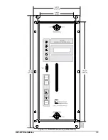
Vertical mount relays are designed to fit into existing panel cutouts for the following case types. No drilling
is necessary.
Basler M1 cases
GE M1 cases
Summary of Contents for BE1-BPR
Page 31: ...BE1 BPR Application 2 17...
Page 42: ...3 4 BE1 BPR Human Machine Interface Figure 3 4 BE1 BPR Relay Vertical Mount Front View...
Page 43: ...BE1 BPR Human Machine Interface 3 5 Figure 3 5 BE1 BPR Relay Vertical Mount Rear View...
Page 49: ...4 6 BE1 BPR Functional Description Figure 4 2 Enhanced BE1 BPR Menu Display Screens...
Page 50: ...BE1 BPR Functional Description 4 7 Figure 4 3 Standard BE1 BPR Menu Display Screens...
Page 94: ...5 4 BE1 BPR BESTlogic Figure 5 1 BESTlogic Function Blocks...
Page 121: ...BE1 BPR Installation 7 3 Figure 7 3 Overall Dimensions Vertical Mount...
Page 122: ...7 4 BE1 BPR Installation Figure 7 4 Overall Dimensions Side View Vertical Mount...
Page 123: ...BE1 BPR Installation 7 5 Figure 7 5 Panel Drilling Diagram Vertical Mount...

