7-8
BE1-BPR Installation
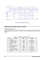
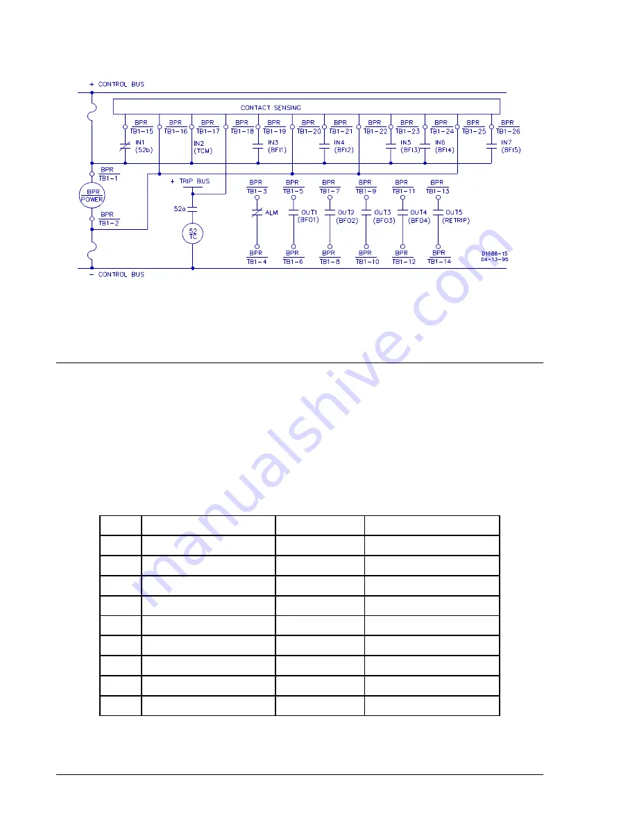
Figure 7-9. Typical External Connections
COMMUNICATION CONNECTORS AND SETTINGS
Front/Rear RS-232 Connectors
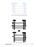
Front and rear RS-232 connectors are DB-9 female connectors. Connector pin numbers, functions, names,
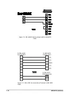
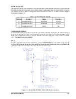
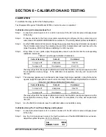
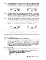
and signal directions are shown in Table 7-1. Figures 7-10 through 7-13 provide RS-232 cable connection
diagrams.
Table 7-1. RS-232 Pinouts (Port0 And Port1A)
Pin
Function
Name
Direction
1
SHIELD
----
N/A
2
TRANSMIT DATA
(TXD)
FROM RELAY
3
RECEIVE DATA
(RXD)
INTO RELAY
4
N/C ----
N/A
5
SIGNAL GROUND
(GND)
N/A
6
DCE READY
(DSR)
FROM RELAY
7
CLEAR TO SEND
(CTS)
INTO RELAY
8
REQUEST TO SEND
(RQS)
FROM RELAY
9
N/C
----
N/A
Summary of Contents for BE1-BPR
Page 31: ...BE1 BPR Application 2 17...
Page 42: ...3 4 BE1 BPR Human Machine Interface Figure 3 4 BE1 BPR Relay Vertical Mount Front View...
Page 43: ...BE1 BPR Human Machine Interface 3 5 Figure 3 5 BE1 BPR Relay Vertical Mount Rear View...
Page 49: ...4 6 BE1 BPR Functional Description Figure 4 2 Enhanced BE1 BPR Menu Display Screens...
Page 50: ...BE1 BPR Functional Description 4 7 Figure 4 3 Standard BE1 BPR Menu Display Screens...
Page 94: ...5 4 BE1 BPR BESTlogic Figure 5 1 BESTlogic Function Blocks...
Page 121: ...BE1 BPR Installation 7 3 Figure 7 3 Overall Dimensions Vertical Mount...
Page 122: ...7 4 BE1 BPR Installation Figure 7 4 Overall Dimensions Side View Vertical Mount...
Page 123: ...BE1 BPR Installation 7 5 Figure 7 5 Panel Drilling Diagram Vertical Mount...

