BE1-BPR Calibration And Testing
8-1
CAL
FREQ
RANGE-1L/2H 60
SECTION 8 • CALIBRATION AND TESTING
CALIBRATION
To calibrate the relay, perform the following steps.
Test Equipment Required: Doble Model F2500 ac current source or equivalent
Calibration Using A Communications Port
Step 1.
Connect all current inputs (A, B, C, and N) in series with the AC current source and apply power
to the relay.
Step 2.
Connect a terminal to the front or rear communications port configured for the protocol shown in
sub-screen 2 of the HMI MAINTENANCE menu branch. (The factory default protocol is 96008N1.)
Step 3.
Use the FREQ command to review or change the power system frequency information as required.
This information determines the sampling rate and filter characteristics and must be set for the
proper frequency (50/60 HZ) before calibrating the A/D converter.
Step 4.
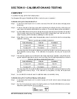
Using Table 8-1 as a guide, apply the appropriate value of current and enter the corresponding
calibration command.
Table 8-1. Low Range Calibration Parameters
Current Sensing
Current
Command
1 ampere CT
2 amperes
CAL1=2
5 ampere CT
10 amperes
CAL1=10
The relay will perform the required calibration and verify that the ADC counts per ampere are within
the acceptable accuracy range. If the calibration is acceptable, the relay will respond with
CAL OK.
Step 5.
This step step applies only to enhanced model relays (high range capability). Using Table 8-2 as
a guide, apply the appropriate value of current and enter the corresponding calibration command.
Table 8-2. High Range Calibration Parameters
Current Sensing
Current
Command
1 ampere CT
2 amperes
CAL1=2
5 ampere CT
10 amperes
CAL1=10
The relay will perform the required calibration and verify that the ADC counts per ampere are within
the acceptable accuracy range. If the calibration is acceptable, the relay will respond with
CAL OK.
Step 6.
Use the SAVE command to save the calibration data in nonvolatile memory.
Calibration Using The Front Panel Display and Keyboard
Step 1.
Connect all current inputs (A, B, C, and N) in series with the AC current source and apply power
to the relay.
Step 2.
Use the front panel keys to select the fourth sub-screen of the MAINTENANCE menu branch.
Adjust the system frequency for 50 or 60 hertz.
Summary of Contents for BE1-BPR
Page 31: ...BE1 BPR Application 2 17...
Page 42: ...3 4 BE1 BPR Human Machine Interface Figure 3 4 BE1 BPR Relay Vertical Mount Front View...
Page 43: ...BE1 BPR Human Machine Interface 3 5 Figure 3 5 BE1 BPR Relay Vertical Mount Rear View...
Page 49: ...4 6 BE1 BPR Functional Description Figure 4 2 Enhanced BE1 BPR Menu Display Screens...
Page 50: ...BE1 BPR Functional Description 4 7 Figure 4 3 Standard BE1 BPR Menu Display Screens...
Page 94: ...5 4 BE1 BPR BESTlogic Figure 5 1 BESTlogic Function Blocks...
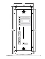
Page 121: ...BE1 BPR Installation 7 3 Figure 7 3 Overall Dimensions Vertical Mount...
Page 122: ...7 4 BE1 BPR Installation Figure 7 4 Overall Dimensions Side View Vertical Mount...
Page 123: ...BE1 BPR Installation 7 5 Figure 7 5 Panel Drilling Diagram Vertical Mount...

