BE1-BPR Maintenance
9-1
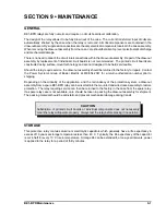
CAUTION
Substitution of printed circuit boards or individual components does not necessarily
mean the relay will operate properly. Always test the relay before placing it in operation.
SECTION 9 • MAINTENANCE
GENERAL
BE1-BPR relays are fully numeric and require no circuit board level calibration.
The design of the relay allows it to be fully drawn out of the case. The current transformer input circuits are
automatically shorted by the case when the relay is removed. All critical components are contained in the
draw-out assembly; suppression capacitors are the only electrical components located in the case assembly.
When removing the draw-out assembly from the case, care should be taken to prevent electrostatic discharge
and mechanical damage.
There is no need to disturb the circuit interconnections within the draw-out assembly. Repair of the draw-out
assembly by replacement of individual circuit boards is not recommended. The printed circuit boards are
constructed using surface-mount technology and are not designed to be field serviceable.
Should the relay require service, the draw-out assembly should be returned to the factory for repair. Contact
the Power Systems Group of Basler Electric at 618/654-2341 for a return authorization number prior to
shipping.
Depending on the criticality of the application, and the redundancy of the protection system, a draw-out
assembly from a spare BE1-BPR relay can be inserted into the mounted and wired case assembly to restore
protection. The relay requiring service can then be returned to the factory in the case from the spare relay.
If a spare relay case is not available, care should be taken in packing the draw-out assembly for shipment.
The packing material should be anti-static and prevent mechanical damage during transit.
STORAGE
This protective relay contains aluminum electrolytic capacitors which generally have a life expectancy in
excess of 10 years at storage temperatures less than 40
(
C. Typically, the life expectancy of the capacitor
is cut in half for every 10
(
C rise in temperature. Storage life can be extended if, at one-year intervals, power
is applied to the relay for a period of thirty minutes.
Summary of Contents for BE1-BPR
Page 31: ...BE1 BPR Application 2 17...
Page 42: ...3 4 BE1 BPR Human Machine Interface Figure 3 4 BE1 BPR Relay Vertical Mount Front View...
Page 43: ...BE1 BPR Human Machine Interface 3 5 Figure 3 5 BE1 BPR Relay Vertical Mount Rear View...
Page 49: ...4 6 BE1 BPR Functional Description Figure 4 2 Enhanced BE1 BPR Menu Display Screens...
Page 50: ...BE1 BPR Functional Description 4 7 Figure 4 3 Standard BE1 BPR Menu Display Screens...
Page 94: ...5 4 BE1 BPR BESTlogic Figure 5 1 BESTlogic Function Blocks...
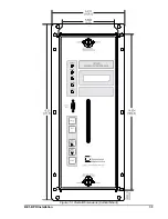
Page 121: ...BE1 BPR Installation 7 3 Figure 7 3 Overall Dimensions Vertical Mount...
Page 122: ...7 4 BE1 BPR Installation Figure 7 4 Overall Dimensions Side View Vertical Mount...
Page 123: ...BE1 BPR Installation 7 5 Figure 7 5 Panel Drilling Diagram Vertical Mount...

