A-2
BE1-BPR Appendix
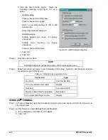
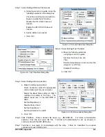
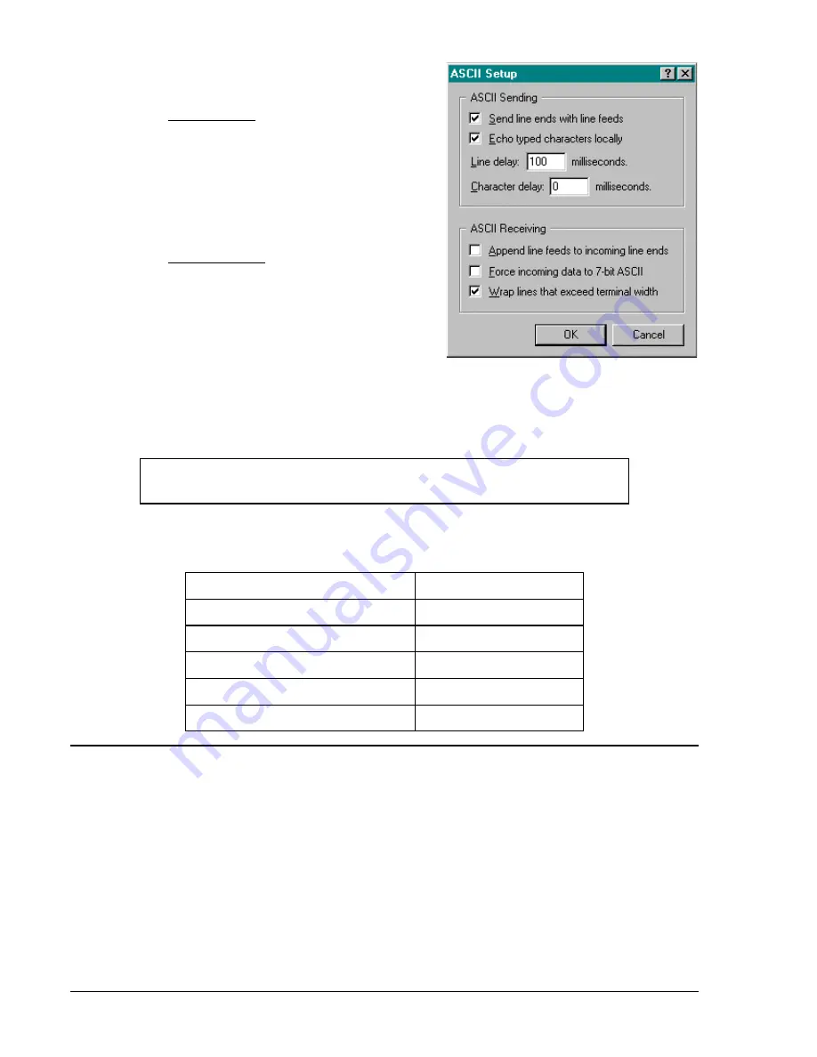
b. Click the ASCII Setup button. Make the
following selections using Figure A-3 as a
guide.
ASCII Sending
Place a check at Send line ends...
Place a check at Echo typed...
Select a line delay setting of 100 to 200
milliseconds.
Select the Character delay at 0.
ASCII Receiving
Disable Append line feeds... by leaving
unchecked.
Disable Force incoming... by leaving
unchecked.
Place a check at Wrap lines...
c. Click “OK”.
d. Click “OK”.
Step 8.
Click File and click Save.
NOTE
Settings changes do not become active until the settings are saved.
Step 9.
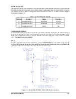
HyperTerminal is now ready to communicate with the relay. Table A-1 describes the required
connection for each RS-232 port.
Table A-1. RS-232 Communication Ports
Connection
Type
Front Port
9 pin, female DCE
PC to Front RS232 port cable
Straight
Rear port
9 pin, female DCE
Modem to Rear RS-232 port cable
Null modem
PC to Rear RS-232 port cable
Straight
WINDOWS
£
TERMINAL
Step 1. In Program Manager, open the Accessories program group and double click the Terminal icon to
start the program.
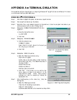
Step 2. On the menu bar, select Settings/Terminal Emulation.
a. In the dialog box, click
DEC VT-100 (ANSI).
b. Click “OK”.
Figure A-3. ASCII Setup Dialog Box
Summary of Contents for BE1-BPR
Page 31: ...BE1 BPR Application 2 17...
Page 42: ...3 4 BE1 BPR Human Machine Interface Figure 3 4 BE1 BPR Relay Vertical Mount Front View...
Page 43: ...BE1 BPR Human Machine Interface 3 5 Figure 3 5 BE1 BPR Relay Vertical Mount Rear View...
Page 49: ...4 6 BE1 BPR Functional Description Figure 4 2 Enhanced BE1 BPR Menu Display Screens...
Page 50: ...BE1 BPR Functional Description 4 7 Figure 4 3 Standard BE1 BPR Menu Display Screens...
Page 94: ...5 4 BE1 BPR BESTlogic Figure 5 1 BESTlogic Function Blocks...
Page 121: ...BE1 BPR Installation 7 3 Figure 7 3 Overall Dimensions Vertical Mount...
Page 122: ...7 4 BE1 BPR Installation Figure 7 4 Overall Dimensions Side View Vertical Mount...
Page 123: ...BE1 BPR Installation 7 5 Figure 7 5 Panel Drilling Diagram Vertical Mount...

