BE1-BPR Appendix
A-3
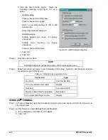
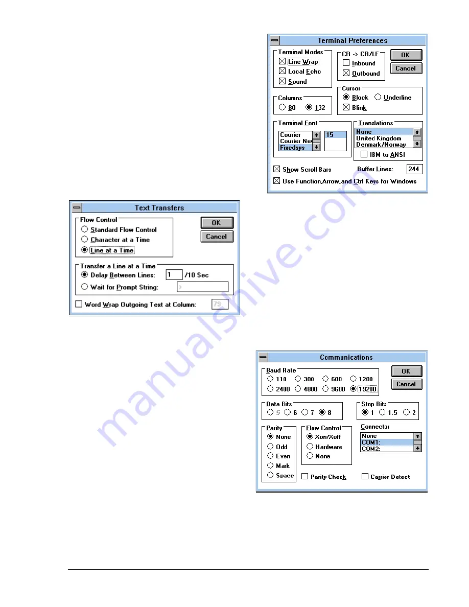
Step 3. Select Settings/Terminal Preferences.
a. Using Figure A-4 as a guide, make the
following selections in the dialog box:
Check the
Line Wrap and Local Echo
boxes to enable these functions.
Disable the
CR->CR/LF Inbound
function.
Enable the
CR->CR/LF Outbound
function.
b. Set the
Buffer Lines at 244.
c. Click “OK”.
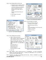
Step 4. Select Settings/Text Transfers
a. Make the following selections
using Figure A-5 as a guide.
Set Flow Control at
Line at a
Time.
Enable
Delay Between Lines and set the
delay at 1 or 2/10 Sec.
Disable
Word Wrap...
b. Click “OK”.
Step 5. Select Settings/Communications
a. Make the following selections:
Under
Connector, select the appropriate
communiation port for your computer.
Adjust the Baud Rate setting so that it
matches the setting of the relay. The
default baud rate of the BE1-BPR is
9600.
rate of the relay is 9600.
Set the Data Bits at
8.
Disable
Parity Check.
Set the Stop Bits
at 1.
Set Flow Control
to Xon/Xoff.
b. Click “OK”.
Step 6. Click File/Save. Enter a desired file name, e.g., BE1-BPR.trm. For future communication
sessions, click File and open this file. Terminal will automatically be set up properly to
communicate with the BE1-BPR relay.
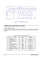
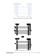
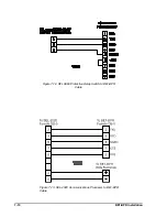
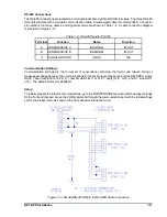
Step 7. Terminal is now ready to communicate with the relay. Table A-1 describes the required
connection for each RS-232 port.
Figure A-4. Terminal Preferences Dialog Box
Figure A-5. Text Transfers Dialog Box
Figure A-6. Communications Dialog Box
Summary of Contents for BE1-BPR
Page 31: ...BE1 BPR Application 2 17...
Page 42: ...3 4 BE1 BPR Human Machine Interface Figure 3 4 BE1 BPR Relay Vertical Mount Front View...
Page 43: ...BE1 BPR Human Machine Interface 3 5 Figure 3 5 BE1 BPR Relay Vertical Mount Rear View...
Page 49: ...4 6 BE1 BPR Functional Description Figure 4 2 Enhanced BE1 BPR Menu Display Screens...
Page 50: ...BE1 BPR Functional Description 4 7 Figure 4 3 Standard BE1 BPR Menu Display Screens...
Page 94: ...5 4 BE1 BPR BESTlogic Figure 5 1 BESTlogic Function Blocks...
Page 121: ...BE1 BPR Installation 7 3 Figure 7 3 Overall Dimensions Vertical Mount...
Page 122: ...7 4 BE1 BPR Installation Figure 7 4 Overall Dimensions Side View Vertical Mount...
Page 123: ...BE1 BPR Installation 7 5 Figure 7 5 Panel Drilling Diagram Vertical Mount...


