C-2
BE1-BPR Appendix
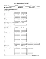
SETTINGS RECORD FOR BE1-BPR
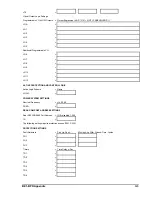
Substation ID
Relay ID
Date
Page
of
BE1-BPR Part Number
Serial Number
Version Number
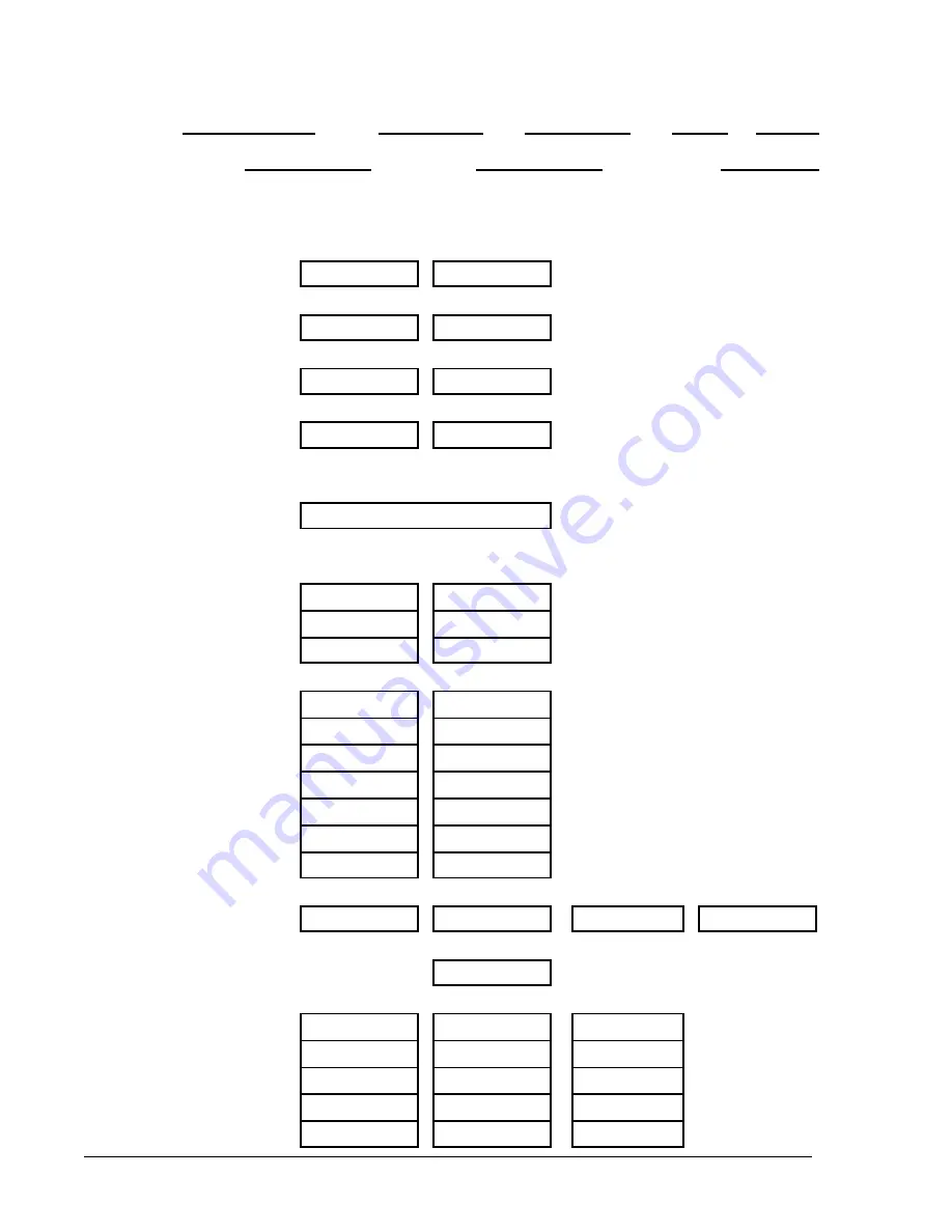
The following settings require global access (PW1).
SECURITY SETTINGS
Global PW and Access Ports
= Password, 8 Char
,
Ports, F,R,B
PW1
=
,
Protection Functions
= Password, 8 Char
,
Ports, F,R,B
PW2
=
,
Breaker Monitoring Functions
= Password, 8 Char
,
Ports, F,R,B
PW3
=
,
Control Functions
= Password, 8 Char
,
Ports, F,R,B
PW4
=
,
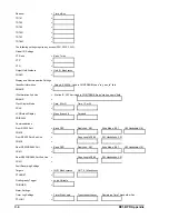
BESTLOGIC SETTINGS FOR USER PROGRAMMABLE LOGIC SCHEME
Name for User Prog Logic
= Name
LN
=
Function Blk Logic Settings
Fault Detectors
= Mode, 0,PI,NI
,
Filter, 1,2,3
LF2
=
,
LF2
=
,
LF3
=
,
Contact Sensing Inputs
= Recognition Time
,
Debounce Time
LI1
=
,
LI2
=
,
LI3
=
,
LI4
=
,
LI5
=
,
LI6
=
,
LI7
=
,
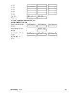
Recloser
= Mode, 0,1,2
,
Start Rcl TD Input
,
Start Reset TD Input
,
Wait Input
LR
=
,
,
,
Recloser-2nd Line
= Delimiters
,
DTL/Blk Input
LR
= ,,,
,
General Purpose Logic Timer
= Mode, 0,C,D
,
Start Input
,
Reset Input
LT1
=
,
,
LT2
=
,
,
LT3
=
,
,
LT4
=
,
,
LT5
=
,
,
Summary of Contents for BE1-BPR
Page 31: ...BE1 BPR Application 2 17...
Page 42: ...3 4 BE1 BPR Human Machine Interface Figure 3 4 BE1 BPR Relay Vertical Mount Front View...
Page 43: ...BE1 BPR Human Machine Interface 3 5 Figure 3 5 BE1 BPR Relay Vertical Mount Rear View...
Page 49: ...4 6 BE1 BPR Functional Description Figure 4 2 Enhanced BE1 BPR Menu Display Screens...
Page 50: ...BE1 BPR Functional Description 4 7 Figure 4 3 Standard BE1 BPR Menu Display Screens...
Page 94: ...5 4 BE1 BPR BESTlogic Figure 5 1 BESTlogic Function Blocks...
Page 121: ...BE1 BPR Installation 7 3 Figure 7 3 Overall Dimensions Vertical Mount...
Page 122: ...7 4 BE1 BPR Installation Figure 7 4 Overall Dimensions Side View Vertical Mount...
Page 123: ...BE1 BPR Installation 7 5 Figure 7 5 Panel Drilling Diagram Vertical Mount...

