BE1-BPR Appendix
C-5
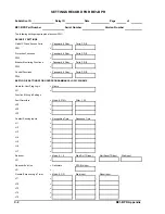
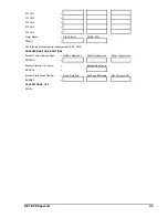
PTLOG2
=
,
,
PTLOG3
=
,
,
PTLOG4
=
,
,
PTLOG5
=
,
,
PTLOG6
=
,
,
Alarm Masks
= DIAG1 (O14)
,
DIAG2 (O15)
PDIAG
=
,
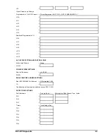
The following settings require breaker access (PW1, PW3).
BREAKER MONITORING SETTINGS
Breaker Contact Duty Settings
= DMAX, x.xxxE+xx,A
2
t
,
Delta t, Contact, msec ,
Delta t, Current, msec
BKRCON
=
,
,
Breaker Status & Op Counter
=
,
Breaker Open Logic
BKROPS
=
,
Breaker Pre-insertion Resister
= Reset Time, Min
,
Max Ops to Blk Reclose ,
Res Current V
PN
/R
BKRRES
=
,
,
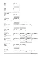
SAVE SETTINGS; YES
SAVE; Y
Summary of Contents for BE1-BPR
Page 31: ...BE1 BPR Application 2 17...
Page 42: ...3 4 BE1 BPR Human Machine Interface Figure 3 4 BE1 BPR Relay Vertical Mount Front View...
Page 43: ...BE1 BPR Human Machine Interface 3 5 Figure 3 5 BE1 BPR Relay Vertical Mount Rear View...
Page 49: ...4 6 BE1 BPR Functional Description Figure 4 2 Enhanced BE1 BPR Menu Display Screens...
Page 50: ...BE1 BPR Functional Description 4 7 Figure 4 3 Standard BE1 BPR Menu Display Screens...
Page 94: ...5 4 BE1 BPR BESTlogic Figure 5 1 BESTlogic Function Blocks...
Page 121: ...BE1 BPR Installation 7 3 Figure 7 3 Overall Dimensions Vertical Mount...
Page 122: ...7 4 BE1 BPR Installation Figure 7 4 Overall Dimensions Side View Vertical Mount...
Page 123: ...BE1 BPR Installation 7 5 Figure 7 5 Panel Drilling Diagram Vertical Mount...

