BE1-BPR Application
2-3
0
2
4
6
8
10
12
14
16
1.05
1.25
2
5
20
40
MULTIPLES OF PICKUP BEFORE DROPOUT
MAX. DROPOUT TIME (ms)
PU=9.99A
PU=5.00A
PU=0.25A
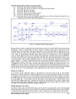
Figure 2-2. Maximum Dropout Timing
20
40
60
80
100
120
140
160
180
1.05
1.25
2
5
20
40
MULTIPLES OF PICKUP
MAX. PICKUP TIME (ms)
PU = 1.00A , 10 CY C
PU = 0.50A , 10 CY C
PU = 0.05A , 10 CY C
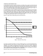
Figure 2-3. Maximum Pickup Timing With 10 Cycle MAF FD
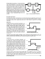
Moving Average Filter Fault Detector Type 2
A moving average filter (MAF) fault detector provides for a slower but more consistent pickup at low current
levels. A MAF fault detector should be used in applications where the current to be detected is less than 0.25
ampere. Typically, the response time for pickup and dropout depends on the number of cycles averaged and
how high the input current is above pickup.
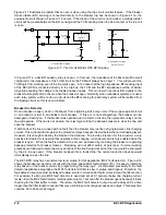
Figure 2-3 shows maximum pickup timing versus current input levels for a 10 cycle MAF fault detector.
This MAF fault detector is programmed by setting the fault detector digital filter selection to 2 (DFLTR2). For
the MAF fault detector to pickup (or dropout), the RMS value of the average of the last 'n' cycles of current
must be above (or below) the pickup setting. Typically, this filter is slow to pickup and slow to dropout but
it is intended for use in low current applications where speed is not critical.
Summary of Contents for BE1-BPR
Page 31: ...BE1 BPR Application 2 17...
Page 42: ...3 4 BE1 BPR Human Machine Interface Figure 3 4 BE1 BPR Relay Vertical Mount Front View...
Page 43: ...BE1 BPR Human Machine Interface 3 5 Figure 3 5 BE1 BPR Relay Vertical Mount Rear View...
Page 49: ...4 6 BE1 BPR Functional Description Figure 4 2 Enhanced BE1 BPR Menu Display Screens...
Page 50: ...BE1 BPR Functional Description 4 7 Figure 4 3 Standard BE1 BPR Menu Display Screens...
Page 94: ...5 4 BE1 BPR BESTlogic Figure 5 1 BESTlogic Function Blocks...
Page 121: ...BE1 BPR Installation 7 3 Figure 7 3 Overall Dimensions Vertical Mount...
Page 122: ...7 4 BE1 BPR Installation Figure 7 4 Overall Dimensions Side View Vertical Mount...
Page 123: ...BE1 BPR Installation 7 5 Figure 7 5 Panel Drilling Diagram Vertical Mount...

