BE1-BPR Application
2-7
8 6
Breaker
Retrip
O 5
IOIT
2 1
IN 2 ( T C M )
Trip Ckt 1 Sense
P
T
5 2 a
5 2 T C 1
N
D 2 8 2 2 - 0 6
0 8 - 0 7 - 9 8
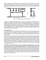
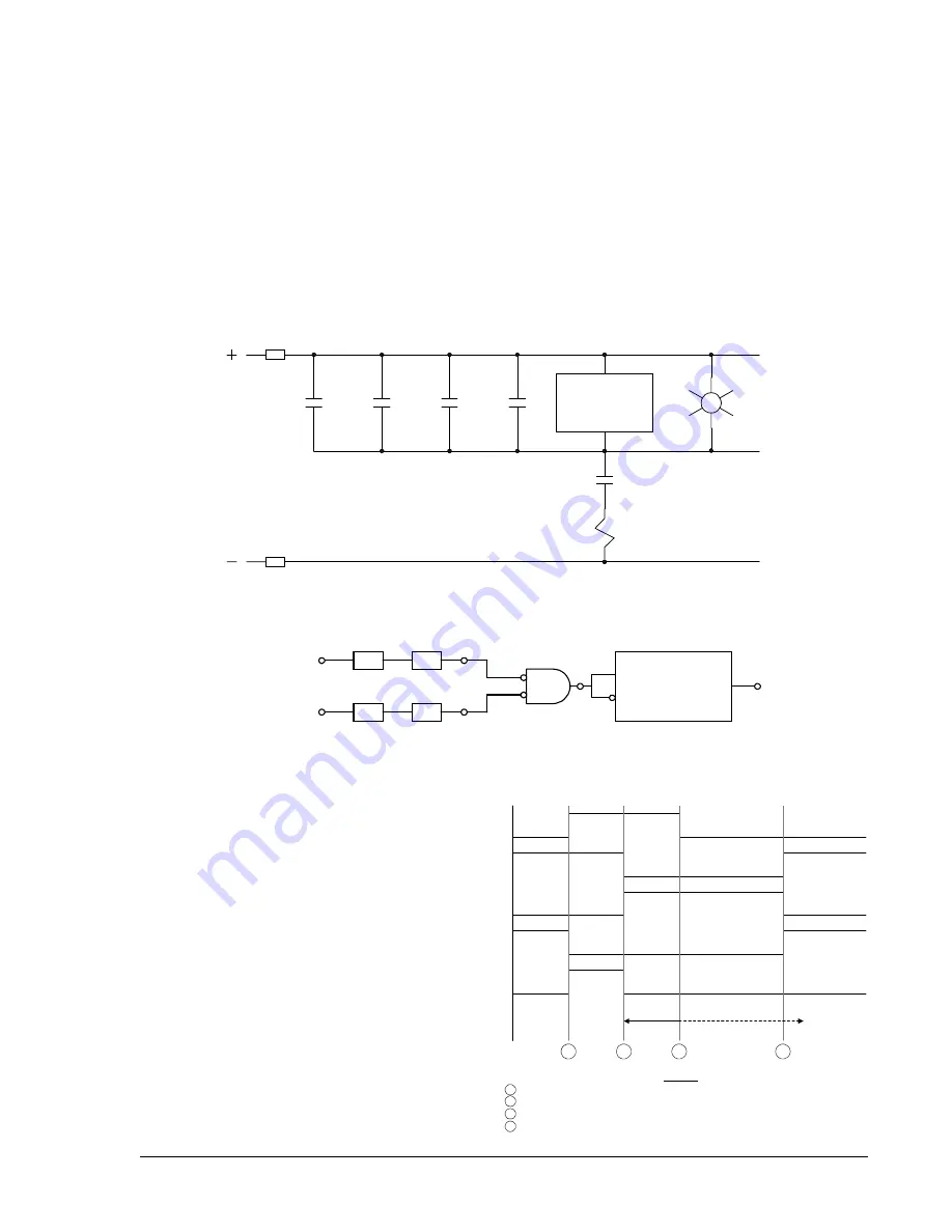
Figure 2-8. Trip Circuit Monitor Schematic Diagram
T 4
A N D
I C S
I C S
LI1
LI2
I1
I2
O 6
IN1
IN2
5 2 b
Trip Circuit
Monitor
D E L A Y T I M E R
S T A R T
R E S E T
O U T
T 4
L T 4
D2822-07
08-07-98
Figure 2-9. Trip Circuit Monitor Logic Diagram
A
LEGEND
Fault occurs, TCM shorted by Line relay
21
Protective Relays
Breaker opens, trip circuit opened
T C M
Trip Circuit Monitor
Relay drops out, trip bus floating
O6
TCM Timer Start
Breaker closed
T4
TCM Timer
Delay Time
2 1
5 2 a
5 2 b
T C M
O 6
T 4
D2822-08
08-07-98
A
B
C
D
B
C
D
Figure 2-10. Trip Circuit Monitor Timing Diagram
logic. If a NC contact is desired, such as for a block reclose signal, then external shorting switches or a low
cost auxiliary relay with NC contacts should be used to allow the electronics to be drawn out.
The ALARM output is a NC contact that is energized to provide a NO signal during normal operation. If the
relay fails or an internal diagnostic signals that an alarm condition exists, the ALARM output deenergizes and
closes the output contacts to signal an alarm condition. If the electronics are drawn out of the case, the
ALARM output also opens.
Trip Circuit Monitor Logic
Logic for monitoring the trip circuit and alarming for loss of voltage (open fuse) or loss of continuity (open trip
coil) is provided in the preprogrammed breaker fail schemes. Figure 2-8 shows input 2 (I2) being used as
a trip circuit monitor (TCM) sensing element. It is placed in parallel with the retrip output of the relay. Figure
2-9 shows a diagram of the logic. If the breaker has multiple trip circuits, an additional input can be used for
TCM sensing with trip circuit 2. For example, if the trip circuit 2 TCM input were input 3 (I3), the expression
for virtual output 6 (O6) would be changed to /I1*/I2+/I1*/I3.
When the breaker is closed, the trip bus T, is at
negative potential through the low impedance
path of the trip coil and the TCM senses a logic
1. Figure 2-10 illustrates the timing of this logic.
When a trip occurs, the trip bus is at positive
potential, the voltage across the TCM is shorted,
and it senses a logic 0. When the breaker
opens, the 52a contact is series with the trip coil
opens, the protective relay drops out, the trip bus
is at positive potential through the high
impedance of the sensing element or the
indicating light (if used), and the TCM continues
to sense a logic 0. The breaker status input
(IN1) in the logic diagram is used to block the
function while the breaker, and therefore, the trip
circuit is open. The timer is used to prevent an
alarm output during the transition between the
closed and open states.
Summary of Contents for BE1-BPR
Page 31: ...BE1 BPR Application 2 17...
Page 42: ...3 4 BE1 BPR Human Machine Interface Figure 3 4 BE1 BPR Relay Vertical Mount Front View...
Page 43: ...BE1 BPR Human Machine Interface 3 5 Figure 3 5 BE1 BPR Relay Vertical Mount Rear View...
Page 49: ...4 6 BE1 BPR Functional Description Figure 4 2 Enhanced BE1 BPR Menu Display Screens...
Page 50: ...BE1 BPR Functional Description 4 7 Figure 4 3 Standard BE1 BPR Menu Display Screens...
Page 94: ...5 4 BE1 BPR BESTlogic Figure 5 1 BESTlogic Function Blocks...
Page 121: ...BE1 BPR Installation 7 3 Figure 7 3 Overall Dimensions Vertical Mount...
Page 122: ...7 4 BE1 BPR Installation Figure 7 4 Overall Dimensions Side View Vertical Mount...
Page 123: ...BE1 BPR Installation 7 5 Figure 7 5 Panel Drilling Diagram Vertical Mount...

