BE1-BPR Human-Machine Interface
3-1
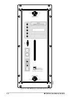
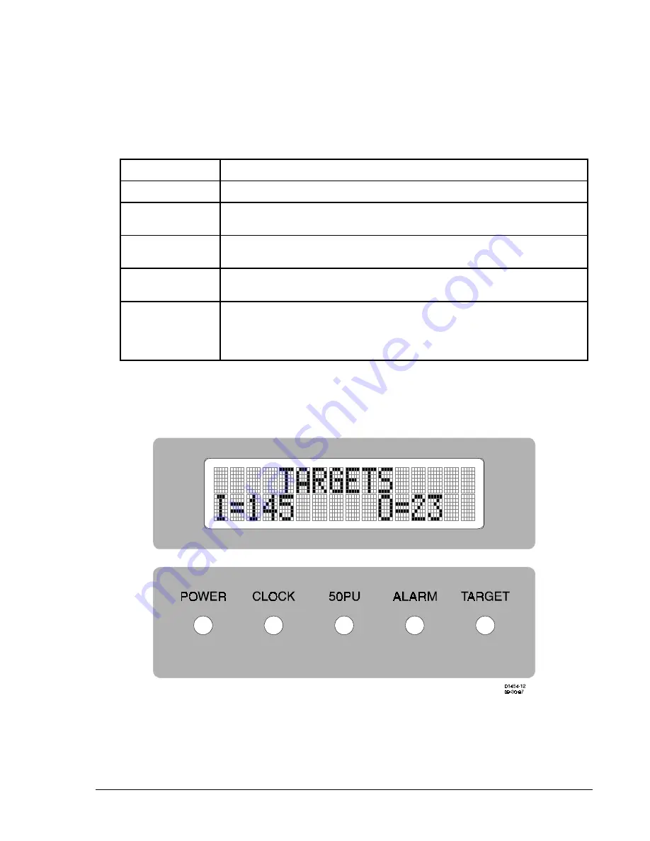
Figure 3-1. BE1-BPR Displays and Indicators
(Vertical Mount Not Shown)
SECTION 3 • HUMAN-MACHINE INTERFACE
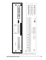
Figures 3-1 and 3-2 show front panel sections for the human-machine interface (HMI). Figures 3-3 through
3-5 show BE1-BPR front and rear views.
Table 3-1. Relay Indicators (Illustrated in Figure 3-1)
Indicator
Function
POWER
GREEN LED that turns ON to indicate power supply is operational.
CLOCK
RED LED that turns ON to indicate that the real-time-clock (RTC) has not
been set.
50PU
RED LED that turns ON to indicate that one or more of the instantaneous
overcurrent pickup settings has been exceeded.
ALARM
RED LED that turns ON to indicate a diagnostic problem with the relay.
TARGET
RED LED that turns ON when one or more of the output relays is energized
and target information has been saved to non-volatile memory. (Detailed
target information is available from the display TARGET MENU.)
Summary of Contents for BE1-BPR
Page 31: ...BE1 BPR Application 2 17...
Page 42: ...3 4 BE1 BPR Human Machine Interface Figure 3 4 BE1 BPR Relay Vertical Mount Front View...
Page 43: ...BE1 BPR Human Machine Interface 3 5 Figure 3 5 BE1 BPR Relay Vertical Mount Rear View...
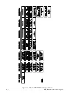
Page 49: ...4 6 BE1 BPR Functional Description Figure 4 2 Enhanced BE1 BPR Menu Display Screens...
Page 50: ...BE1 BPR Functional Description 4 7 Figure 4 3 Standard BE1 BPR Menu Display Screens...
Page 94: ...5 4 BE1 BPR BESTlogic Figure 5 1 BESTlogic Function Blocks...
Page 121: ...BE1 BPR Installation 7 3 Figure 7 3 Overall Dimensions Vertical Mount...
Page 122: ...7 4 BE1 BPR Installation Figure 7 4 Overall Dimensions Side View Vertical Mount...
Page 123: ...BE1 BPR Installation 7 5 Figure 7 5 Panel Drilling Diagram Vertical Mount...

