BE1-BPR Functional Description
4-1
SECTION 4 • FUNCTIONAL DESCRIPTION
GENERAL
BE1-BPR Breaker Protection Relays are microprocessor-based devices that provide breaker failure pro-
tection, optional fault recording, and diagnostic monitoring of breaker wear and breaker resistor overheating.
This section describes the hardware and software functional descriptions.
HARDWARE FUNCTIONAL DESCRIPTION
BPRs are available as either 19 inch rack mount units or vertical panel mount units. The rack mount is
approximately 3.48 inches high and the vertical panel mount is about 5.38 inches wide and 14.32 inches
high. The vertical panel mount unit assemblies are arranged differently to fit the 14.32 inch casing. A trans-
parent front cover protects the unit but allows access to some front panel controls. A spring loaded handle
under the front cover retracts when released and provides drawout capability of the BPR relay (chassis
assembly) from the rack assembly. It is not necessary to disturb system wiring when removing a BPR relay
from the case.
The hardware function description is divided into three categories: inputs, circuit operation, and outputs.
Inputs
There are five types of inputs to the BPR relay. They are:
Operating Power
Contact Sensing
Current Sensing
Keyboard
Serial Ports RS-232/RS-485
Operating Power
Operating power for the internal circuitry is applied to the isolated internal switching power supply. Required
operating power is either 48/125 VDC or 125/250 VDC and is determined by the relay part number shown
in Section 1,
General Information, Specifications.
Contact Sensing
Seven external contact sensing inputs provide external stimulus to initiate BPR relay actions. Nominal volt-
age(s) of the external dc source(s) must fall within the relay DC power supply input voltage range. If the
power supply of the relay has an ac source, a separate dc source must be used for the contact sensing input
voltage. Three contact sensing inputs (IN1 through IN3) are individually isolated. IN4 and IN5 are isolated
from other circuits but share a common return. IN6 and IN7 are also isolated from other circuits but share
a common return.
Current Sensing
Monitored line and neutral currents are applied to internal current transformer primaries and stepped down
to internal circuit levels. The internal current transformers provide isolation from the monitored line currents.
Keyboard
A five key keyboard (illustrated in Section 3) provides limited local programming capability and the ability
to select a number of status and diagnostic menu screens.
Summary of Contents for BE1-BPR
Page 31: ...BE1 BPR Application 2 17...
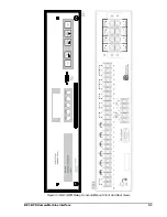
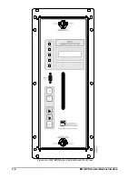
Page 42: ...3 4 BE1 BPR Human Machine Interface Figure 3 4 BE1 BPR Relay Vertical Mount Front View...
Page 43: ...BE1 BPR Human Machine Interface 3 5 Figure 3 5 BE1 BPR Relay Vertical Mount Rear View...
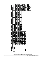
Page 49: ...4 6 BE1 BPR Functional Description Figure 4 2 Enhanced BE1 BPR Menu Display Screens...
Page 50: ...BE1 BPR Functional Description 4 7 Figure 4 3 Standard BE1 BPR Menu Display Screens...
Page 94: ...5 4 BE1 BPR BESTlogic Figure 5 1 BESTlogic Function Blocks...
Page 121: ...BE1 BPR Installation 7 3 Figure 7 3 Overall Dimensions Vertical Mount...
Page 122: ...7 4 BE1 BPR Installation Figure 7 4 Overall Dimensions Side View Vertical Mount...
Page 123: ...BE1 BPR Installation 7 5 Figure 7 5 Panel Drilling Diagram Vertical Mount...

