4-2
BE1-BPR Functional Description
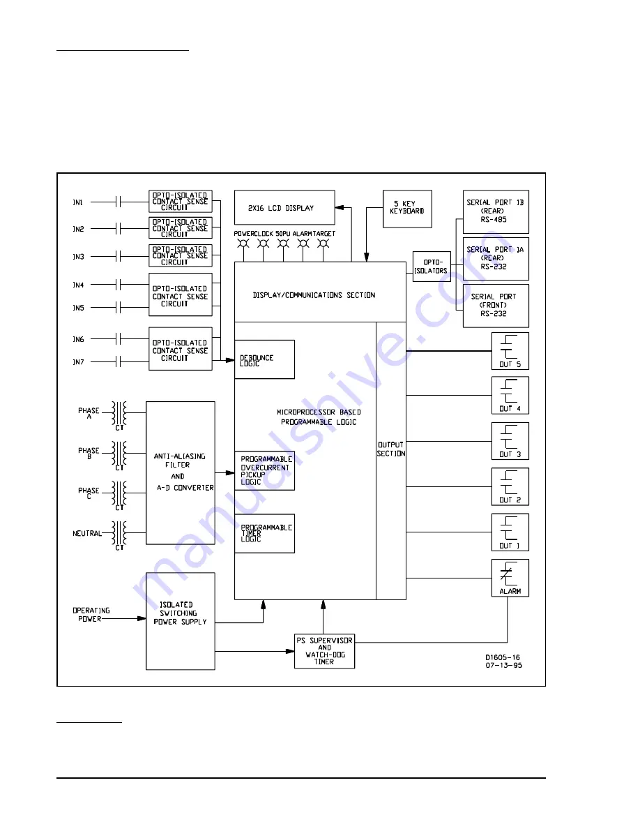
Figure 4-1. Functional Block Diagram
Serial Ports RS-232/RS-485
Serial communication ports at the front and rear of the BPR relay provide total programming capability and
remote access for diagnostic, relay setup, and control.
Circuit Operation
The microprocessor continually monitors itself to ensure proper operation. Separate, independent circuitry
monitors the power supply and the microprocessor to ensure that any problem in these areas automatically
takes the BPR Relay off-line and activates the alarm output. Relay circuit functions illustrated in Figure 4-1
are described in the following paragraphs.
Power Supply
The isolated switching power supply generates ±12 Vdc, +5 Vdc, and an is5 Vdc. If the +5 Vdc
digital supply falls outside the defined tolerance, then the microprocessor will be reset by the power supply
supervisory circuit. This reset takes the relay off-line and lights the ALARM LED.
Summary of Contents for BE1-BPR
Page 31: ...BE1 BPR Application 2 17...
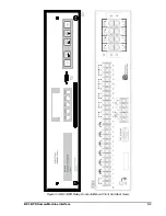
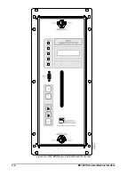
Page 42: ...3 4 BE1 BPR Human Machine Interface Figure 3 4 BE1 BPR Relay Vertical Mount Front View...
Page 43: ...BE1 BPR Human Machine Interface 3 5 Figure 3 5 BE1 BPR Relay Vertical Mount Rear View...
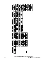
Page 49: ...4 6 BE1 BPR Functional Description Figure 4 2 Enhanced BE1 BPR Menu Display Screens...
Page 50: ...BE1 BPR Functional Description 4 7 Figure 4 3 Standard BE1 BPR Menu Display Screens...
Page 94: ...5 4 BE1 BPR BESTlogic Figure 5 1 BESTlogic Function Blocks...
Page 121: ...BE1 BPR Installation 7 3 Figure 7 3 Overall Dimensions Vertical Mount...
Page 122: ...7 4 BE1 BPR Installation Figure 7 4 Overall Dimensions Side View Vertical Mount...
Page 123: ...BE1 BPR Installation 7 5 Figure 7 5 Panel Drilling Diagram Vertical Mount...


