BE1-BPR Functional Description
4-3
Watchdog Timer
If the microprocessor fails for any reason, output pulses to the watch-dog timer stop. After a short duration
of time, the watch-dog timer will take the relay off-line and turn on the ALARM LED and close the alarm
output.
Opto-Isolators
Opto-isolators in the contact sensing input circuits provide isolation from the external power supply which
provides power to the contact input circuits.
Debounce Logic
Outputs from the contact sensing circuits are debounced by the microprocessor using programmable
recognition and debounce times. Debounce logic is programmable only through the communication ports.
Anti-Aliasing Filter and A/D Converter
Stepped down inputs from each current transformer are converted to a voltage signal and filtered by a low-
pass anti-aliasing filter. The digitized input signal is then passed to the microprocessor for processing.
Programmable Fault Detector Logic
Each monitored current is digitized and digitally filtered and the 50/60 HZ RMS value for each input is calcu-
lated. The filtered value is compared to the appropriate pickup setting. If the filtered value is greater than
the pickup setting, then a fault detector logic flag (F1, F2, or F3) is set for use by the output logic section.
If the fault detector logic is programmed as an instantaneous overcurrent pickup (Filter Type 1 or 3), the
50PU LED is turned on. If the fault detector logic is programmed as a moving average current detector,
(Filter Type 2), the 50PU LED is not turned on.
Programmable Timer Logic
Up to six programmable, independent timers are available in the breaker fail logic. The timers can be
programmed to act as a control timer or delay timer.
Programmable Recloser Logic
A one to three shot recloser function is available with separate timers for reset, reclose fail, and maximum
cycle time.
Microprocessor Based Programmable Logic
Microprocessor software provides the capability of a programmable logic controller (PLC) to control the
outputs. Output control equations take the form of simple boolean equations. Contact inputs (Ix), fault
detectors (Fx), timer outputs (Tx), and outputs relays (Ox) act as variables in the equations. The micropro-
cessor based programmable logic is covered in detail in Section 5,
BESTlogic Programmable Logic.
Outputs
There are five types of outputs from the BPR relay. They are:
ALARM Relay
Output Relays
Targets
LCD Display
Serial Ports RS-232/RS-485
Summary of Contents for BE1-BPR
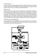
Page 31: ...BE1 BPR Application 2 17...
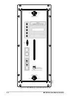
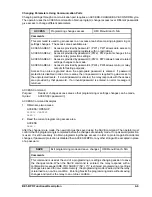
Page 42: ...3 4 BE1 BPR Human Machine Interface Figure 3 4 BE1 BPR Relay Vertical Mount Front View...
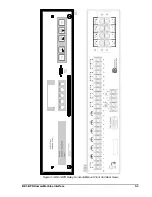
Page 43: ...BE1 BPR Human Machine Interface 3 5 Figure 3 5 BE1 BPR Relay Vertical Mount Rear View...
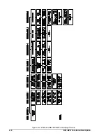
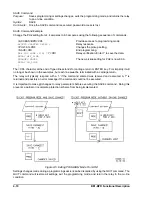
Page 49: ...4 6 BE1 BPR Functional Description Figure 4 2 Enhanced BE1 BPR Menu Display Screens...
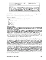
Page 50: ...BE1 BPR Functional Description 4 7 Figure 4 3 Standard BE1 BPR Menu Display Screens...
Page 94: ...5 4 BE1 BPR BESTlogic Figure 5 1 BESTlogic Function Blocks...
Page 121: ...BE1 BPR Installation 7 3 Figure 7 3 Overall Dimensions Vertical Mount...
Page 122: ...7 4 BE1 BPR Installation Figure 7 4 Overall Dimensions Side View Vertical Mount...
Page 123: ...BE1 BPR Installation 7 5 Figure 7 5 Panel Drilling Diagram Vertical Mount...

