BE1-BPR Functional Description
4-5
NOTE
Relay responses in all examples are displayed in a
Courier
typeface.
HELP Command
Purpose:
Obtains helpful information about communication port commands.
Syntax:
HELP[x/<cmd>]
Comments:
No access area password is required to use the HELP command.
HELP Command Example
Obtain information about using the PU command.
HELP PU
Purpose: Read/Change fault detector Pickup level and cycles
Syntax : PU[#[=<level(A)>[,<cycles>]]]
Example: PU1 or PU1=6.2 or PU3=0.5,10
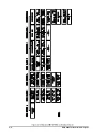
Startup And Menu Selection
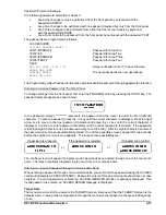
When the relay is turned on, the start-up screen is displayed for two seconds and then defaults to the TAR-
GETS menu screen. At this time the relay is at the menu level. Operating the front panel right arrow key
causes each menu screen to be displayed in succession. The display order is:
0.
TARGETS
4.
TIMER LOG
1.
RELAY SETUP
5.
FAULT LOG (Enhanced units only)
2.
RELAY STATUS
6.
MAINTENANCE
3.
BREAKER STATUS
After MAINTENANCE, the menu returns to the TARGETS screen.
Viewing Screens
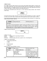
All display menu screens are easily viewed using the right and down arrow keys. For example, there are
three sub-screens under the RELAY SETUP screen. Timer delay settings for timers T4, T5, and T6 (TD4,
TD5, and TD6) are shown in the third sub-screen. To view these settings, use the right arrow key until you
see the RELAY SETUP menu screen on the front panel display. Use the down arrow key until you see the
third sub-screen. Follow this same procedure to view any sub-screen in any menu screen.
Default Screen
Default screens are automatically displayed if no keys have been pressed for five minutes. The standard
default screen is the target screen. The user has the option to default to another screen (e.g. — current
display, breaker operations counter, time/date) when no targets are active by using the PDISPLAY com-
mand. More information about the PDISPLAY command is provided in the
Maintenance sub-section.
Changing Parameters Using the Front Panel
Changing settings through the front panel consists of an ACCESS-CHANGE-SAVE-CONFIRM cycle. Chang-
ing parameters requires that you access the programming mode, select the appropriate screen(s), program
(make) the change(s), save new relay setting(s) and confirm that the programming is completed before the
changes are actually made. The relay continues to use the previous setting parameters until all changes
are made and the new settings are saved. It is important to change all relay parameters and then execute
the SAVE command. Doing this prevents partial or incomplete protection schemes from being implemented.
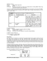
As an example, in order to change the overcurrent pickup setting for PU2 from 4.4 amperes to 6.3 amperes,
the following procedures would be used.
Accessing PROGRAM Mode
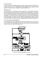
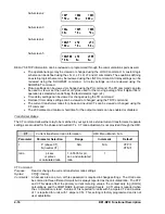
To access the PROGRAM mode, press the PROG key. If password protection is enabled, you will be
prompted to enter the password before continuing. For now, let's assume that we have not enabled
password protection. An access level screen will be displayed momentarily showing your programming
access level and then the original display will return and a cursor will be visible.
Summary of Contents for BE1-BPR
Page 31: ...BE1 BPR Application 2 17...
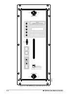
Page 42: ...3 4 BE1 BPR Human Machine Interface Figure 3 4 BE1 BPR Relay Vertical Mount Front View...
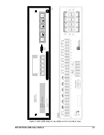
Page 43: ...BE1 BPR Human Machine Interface 3 5 Figure 3 5 BE1 BPR Relay Vertical Mount Rear View...
Page 49: ...4 6 BE1 BPR Functional Description Figure 4 2 Enhanced BE1 BPR Menu Display Screens...
Page 50: ...BE1 BPR Functional Description 4 7 Figure 4 3 Standard BE1 BPR Menu Display Screens...
Page 94: ...5 4 BE1 BPR BESTlogic Figure 5 1 BESTlogic Function Blocks...
Page 121: ...BE1 BPR Installation 7 3 Figure 7 3 Overall Dimensions Vertical Mount...
Page 122: ...7 4 BE1 BPR Installation Figure 7 4 Overall Dimensions Side View Vertical Mount...
Page 123: ...BE1 BPR Installation 7 5 Figure 7 5 Panel Drilling Diagram Vertical Mount...

