4-10
BE1-BPR Functional Description
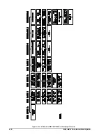
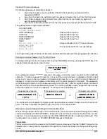
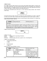
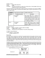
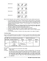
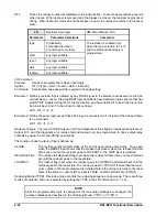
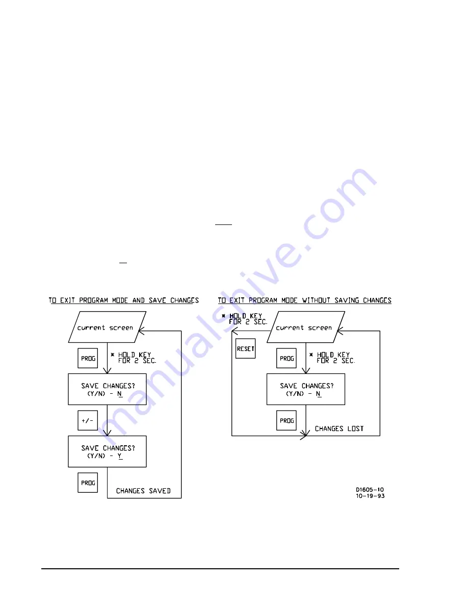
Figure 4-5. Exiting PROGRAM Mode From HMI
SAVE Command
Purpose:
Saves programming or settings changes, exits the programming mode, and returns the relay
to an on-line condition.
Syntax:
SAVE
Comments:
Once the SAVE command is executed, password access is lost.
SAVE Command Example
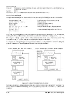
Change the PU2 setting from 4.4 amperes to 6.3 amperes using the following sequence of commands.
>ACCESS=BPR<CR>
Provides access to programming mode.
ACCESS GRANTED LEVEL 1
Relay response.
>PU2=6.3<CR>
Changes the pickup setting.
>SAVE<CR>
End programming.
ARE YOU SURE (Y/N) ?
Y<CR>
Relay verification. Enter Y to save the data.
RELAY OFF_LINE
CHANGES SAVED
The new pickup setting for PU2 is now 6.3 A.
RELAY ON_LINE
>
The <CR> character at the end of typed lines stands for carriage return or ENTER key. For simplicity it will
no longer be shown in the examples, but each line must be terminated with a carriage return.
The relay will typically respond with a '>' if the command entered was received and executed. A '?' is
returned and possibly an error message if the command could not be executed.
It is important to make all changes to relay parameters before executing the SAVE command. Doing this
prevents a partial or incomplete protection scheme from being implemented.
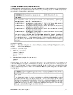
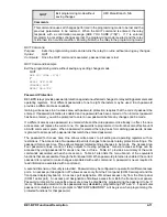
Settings changes made during a programming session can be discarded by using the QUIT command. The
QUIT command will restore all settings, exit the programming mode, and return the relay to the on-line
condition.
Summary of Contents for BE1-BPR
Page 31: ...BE1 BPR Application 2 17...
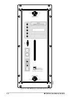
Page 42: ...3 4 BE1 BPR Human Machine Interface Figure 3 4 BE1 BPR Relay Vertical Mount Front View...
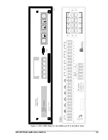
Page 43: ...BE1 BPR Human Machine Interface 3 5 Figure 3 5 BE1 BPR Relay Vertical Mount Rear View...
Page 49: ...4 6 BE1 BPR Functional Description Figure 4 2 Enhanced BE1 BPR Menu Display Screens...
Page 50: ...BE1 BPR Functional Description 4 7 Figure 4 3 Standard BE1 BPR Menu Display Screens...
Page 94: ...5 4 BE1 BPR BESTlogic Figure 5 1 BESTlogic Function Blocks...
Page 121: ...BE1 BPR Installation 7 3 Figure 7 3 Overall Dimensions Vertical Mount...
Page 122: ...7 4 BE1 BPR Installation Figure 7 4 Overall Dimensions Side View Vertical Mount...
Page 123: ...BE1 BPR Installation 7 5 Figure 7 5 Panel Drilling Diagram Vertical Mount...


