4-12
BE1-BPR Functional Description
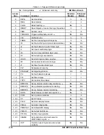
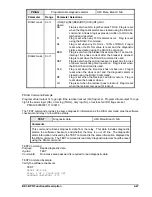
Table 4-1. Password Write Access Areas
NA = Not applicable
L
= Enhanced units only
HMI Menu Branch
Access
Area
Command
Function
Standard
Models
Enhanced
Models
0
DATE
Set clock date
5
6
0
DIAG
Reset alarms
2
2
0
FLOG
Reset fault log
L
NA
5
0
RESET
Reset targets or reset other logs if specified
0
0
0
TIME
Set time clock
5
6
0
TRIGGER
Trigger oscillography record
L
NA
NA
1
CAL
Calibrate relay
5
6
1
FREQ
Set the nominal system frequency
5
6
1
ID
Set the multi-drop communications address
NA
NA
1
LF
Set fault detector function block logic
NA
NA
1
LI
Set input conditioning logic
NA
NA
1
LN
Set user programmable logic name
NA
NA
1
LO
Set output logic expressions
NA
NA
1
LOGIC
Set which logic scheme is active
NA
NA
1
LR
Set recloser function block logic
NA
NA
1
LT
Set timer function block logic
NA
NA
1
PW
Set password security
5
6
1, 2
PTARGET
Set targeting function
NA
NA
1, 2
PU
Set fault detector pickups
1
1
1, 2
TD
Set timer delays
1
1
1, 2
TD79
Set recloser time delays
1
1
1, 3
BKRCON
Set up breaker contact duty monitoring
L
NA
NA
1, 3
BKROPS
Set up breaker operations monitoring
NA
NA
1, 3
BKRRES
Set up breaker resistor monitoring
NA
NA
1, 3
DLOG
Reset breaker contact duty registers
L
NA
3
1, 2, 3
COM
Set up communications
5
6
1, 2, 3
CT
Set CT ratios
NA
NA
1, 2, 3
PCLK
Set clock display format
NA
NA
1, 2, 3
PDIAG
Set alarm diagnostics
NA
NA
1, 2, 3
PDISPLAY
Set default HMI display
NA
NA
1, 2, 3
PHOLD
Set output hold timers
NA
NA
1, 2, 3
PTLOG
Set timer log operation
NA
NA
1, 2, 3
SNAME
Set substation and circuit name for
COMTRADE reports
L
NA
NA
1, 4
OUT
Override output logic and pulse output
contacts
NA
NA
Summary of Contents for BE1-BPR
Page 31: ...BE1 BPR Application 2 17...
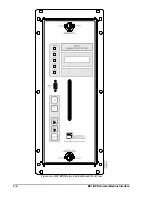
Page 42: ...3 4 BE1 BPR Human Machine Interface Figure 3 4 BE1 BPR Relay Vertical Mount Front View...
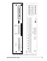
Page 43: ...BE1 BPR Human Machine Interface 3 5 Figure 3 5 BE1 BPR Relay Vertical Mount Rear View...
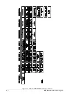
Page 49: ...4 6 BE1 BPR Functional Description Figure 4 2 Enhanced BE1 BPR Menu Display Screens...
Page 50: ...BE1 BPR Functional Description 4 7 Figure 4 3 Standard BE1 BPR Menu Display Screens...
Page 94: ...5 4 BE1 BPR BESTlogic Figure 5 1 BESTlogic Function Blocks...
Page 121: ...BE1 BPR Installation 7 3 Figure 7 3 Overall Dimensions Vertical Mount...
Page 122: ...7 4 BE1 BPR Installation Figure 7 4 Overall Dimensions Side View Vertical Mount...
Page 123: ...BE1 BPR Installation 7 5 Figure 7 5 Panel Drilling Diagram Vertical Mount...

