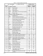
BE1-BPR Functional Description
4-17
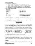
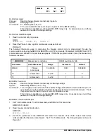
CT Command Examples
1.
Enter a Neutral CT ratio of 400:5.
CTN=80
or CTN=400/5 or CTN=400:5
2.
Read the CT ratios.
CT
CTP=50; CTN=80
Fault Detectors
Three fault detectors, F1, F2, and F3, are provided in the BE1-BPR. Each fault detector can be configured
for phase or neutral current sensing and the type of filtering. Three filtering options are available:
Instantaneous (Type 1), Moving Average (Type 2), and Instantaneous Three Phase (Type 3).
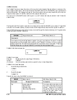
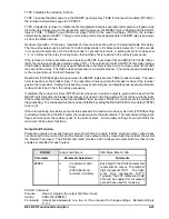
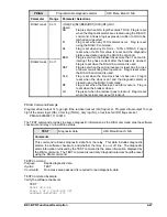
Type 1 Fault Detector. The Type 1 fault detector provides high speed operation with a typical pickup time
of one cycle and a typical dropout time of ¼ cycle. Fault detectors F1 and F2 are programmed as Type 1
fault detectors in the pre-programmed logic schemes. Refer to Section 2,
Application for a detailed
description of the Type 1 fault detector.
Type 2 Fault Detector. The Type 2 fault detector provides a slower but more consistent pickup. This type
of fault detector is appropriate for applications where fault detector sensitivity of less than 0.25 amperes
(relays with 5 ampere current sensing) is desirable. When a Type 2 fault detector is used, the pickup (PU)
command includes a parameter for entering the number of cycles to be averaged before pickup or dropout
occurs. Refer to Section 2,
Application for a detailed description of the Type 2 fault detector.
Type 3 Fault Detector. The Type 3 fault detector performance is identical to the Type 1 fault detector except
that all three phase currents must be above the pickup threshold to get an output. Refer to Section 2,
Application for a detailed description of the Type 3 fault detector.
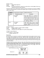
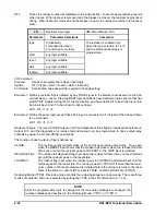
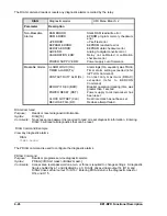
The LF command configures each fault detector for phase or neutral protection and for high speed or moving
average filtering.
LF
Fault detector logic
HMI Menu Branch: N/A
Parameter
Parameter Selections
Defaults
type
PI (phase overcurrent)
NI (neutral overcurrent)
LF1=PI,1
LF2=NI,1
LF3=PI,2
filter
1 (1 cycle RMS filter)
2 (moving average filter)
3 (1 cycle RMS 3-phase filter)
LF Command
Purpose:
Read or change the fault detector logic of the active logic scheme
Syntax:
LF[x][=<type>,<filter>]
Comments:
An access area one password is required to change settings.
LF Command Examples
1.
Program fault detector 1 as a phase overcurrent fault detector using digital filter 1.
LF1=PI,1
2.
Program fault detector 2 as a neutral overcurrent fault detector using digital filter 1.
LF2=NI,1
3.
Program fault detector 3 as a phase overcurrent pickup using the moving average filter (filter 2).
LF3=PI,2
Summary of Contents for BE1-BPR
Page 31: ...BE1 BPR Application 2 17...
Page 42: ...3 4 BE1 BPR Human Machine Interface Figure 3 4 BE1 BPR Relay Vertical Mount Front View...
Page 43: ...BE1 BPR Human Machine Interface 3 5 Figure 3 5 BE1 BPR Relay Vertical Mount Rear View...
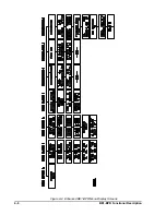
Page 49: ...4 6 BE1 BPR Functional Description Figure 4 2 Enhanced BE1 BPR Menu Display Screens...
Page 50: ...BE1 BPR Functional Description 4 7 Figure 4 3 Standard BE1 BPR Menu Display Screens...
Page 94: ...5 4 BE1 BPR BESTlogic Figure 5 1 BESTlogic Function Blocks...
Page 121: ...BE1 BPR Installation 7 3 Figure 7 3 Overall Dimensions Vertical Mount...
Page 122: ...7 4 BE1 BPR Installation Figure 7 4 Overall Dimensions Side View Vertical Mount...
Page 123: ...BE1 BPR Installation 7 5 Figure 7 5 Panel Drilling Diagram Vertical Mount...

