4-18
BE1-BPR Functional Description
CAUTION
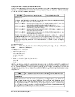
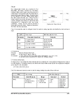
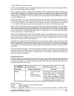
A pickup setting range check is made each time logic settings are changed that affect the fault
detector pickup settings. For example, if PU1=5.00 and LF1 setting is changed from PI,1 to PI,2,
the PU1 setting will automatically change from 5.00 to 1.00 (the maximum allowable setting for
a Type 2 fault detector on a 5 A unit). This kind of pickup setting adjustment can also occur if the
active relay logic is replaced with logic that has different LF settings.
38
38
38
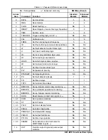
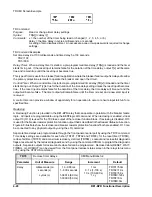
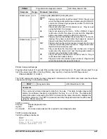
The PU command sets the trip value of each fault detector and the moving average filter cycles for Type 2
fault detectors.
PU
Fault detector pickup levels
HMI Menu Branch: 1
Parameter
Unit of Measure
Range
Increment
Default
level
5 A CT
LFx=type,1 or 3
amperes
0.25 - 9.99
0.01
PU1=8.00
PU2=2.00
PU3=0.50,10
level
5 A CT
LFx=type,2
amperes
0.05 - 1.00
0.01
level
1 A CT
LFx=type,1 or 3
amperes
0.05 - 2.00
0.01
PU1=2.00
PU2=2.00
PU3=0.20,10
level
1 A CT
LFx=type,2
amperes
0.01 - 0.10
0.01
cycles
cycles
1 - 100
1
N/A
NOTE: Types 1 and 3 PU settings can be set below the stated minimum settings. However,
specified accuracies will not be maintained when PU settings are set outside the setting range.
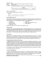
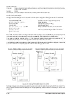
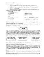
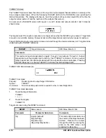
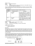
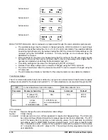
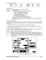
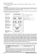
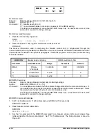
PU HMI Screen Example
PU Command
Purpose:
Read or change fault detector pickup levels
Syntax:
PU[x] [=<level>[,<cycles>]]
Comments:
x = 1 (fault detector 1), 2 (fault detector 2), or 3 (fault detector 3)
level = pickup level in amperes for fault detector x
cycles = number of moving average filter cycles
Cycles parameter is used only if an analog channel is programmed to have a moving average
filter (Lfx=type,2). See LF command information in
BESTlogic Functions section. An access
area one or two password is required to change settings.
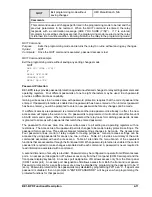
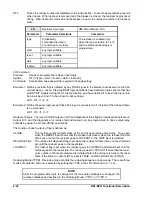
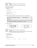
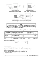
PU Command Examples
1.
Set the analog channel pickup level at 6.2 amperes.
PU1=6.2
2.
Read the pickup setting for all channels.
PU
PU1=6.2; PU2=0.5; PU3=0.1,10
Summary of Contents for BE1-BPR
Page 31: ...BE1 BPR Application 2 17...
Page 42: ...3 4 BE1 BPR Human Machine Interface Figure 3 4 BE1 BPR Relay Vertical Mount Front View...
Page 43: ...BE1 BPR Human Machine Interface 3 5 Figure 3 5 BE1 BPR Relay Vertical Mount Rear View...
Page 49: ...4 6 BE1 BPR Functional Description Figure 4 2 Enhanced BE1 BPR Menu Display Screens...
Page 50: ...BE1 BPR Functional Description 4 7 Figure 4 3 Standard BE1 BPR Menu Display Screens...
Page 94: ...5 4 BE1 BPR BESTlogic Figure 5 1 BESTlogic Function Blocks...
Page 121: ...BE1 BPR Installation 7 3 Figure 7 3 Overall Dimensions Vertical Mount...
Page 122: ...7 4 BE1 BPR Installation Figure 7 4 Overall Dimensions Side View Vertical Mount...
Page 123: ...BE1 BPR Installation 7 5 Figure 7 5 Panel Drilling Diagram Vertical Mount...

