BE1-BPR Functional Description
4-23
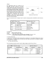
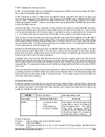
TYPE 0 disables the reclosing function.
TYPE 1 requires that after power-up, the RESET input logic stay TRUE for the reset time delay (TD79R) or
the recloser automatically goes to LOCKOUT.
TYPE 2 allows the recloser to initiate the first programmed reclose operation after power-up if power was
lost when the recloser was in the reset state and at power-up, the RESET logic is FALSE and the START
logic is TRUE. If RESET goes TRUE and stays TRUE for the reset time delay (TD79R), the recloser
automatically goes to RESET. This type of reclosing mode may be appropriate if the BPR relay is powered-
up from the station service.
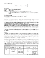
Recloser Operation. There are a maximum of three reclose shots, each with a programmable time delay.
The three time delays can be set from 10 to 999 milliseconds in 1 milliseconds increments, 1 to 99 seconds
in 0.1 second increments, or 100 to 600 seconds in 1 second increments. A setting of zero for reclose shot
1, 2, or 3 will send the relay to lockout when that reclose shot is reached in the reclosing sequence.
If the recloser is in the reset state upon receiving a START input signal (RI) and RESET is FALSE (52a or
/52b), the reclose logic issues a reclose output (O13). The output occurs after the TD791 time delay setting.
If the breaker closes and then opens again before the reset timer is timed out, a reclose output occurs after
the second time delay. The third reclose output occurs in a similar manner. The recloser goes immediately
to the lockout state on the fourth breaker trip.
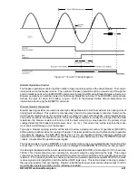
Reset timer (TD79R) begins timing out when the RESET logic becomes TRUE (breaker closes). The reset
timer is reset when the breaker trips. If the reset timer times out while the breaker is closed, the recloser
goes to the reset state. Setting the reset time delay at zero will give an instantaneous reset and eliminate
reclose shots 2 and 3 from the reclose sequence.
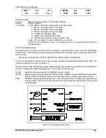
If enabled, the reclose fail timer (TD79F) starts whenever a reclose output is given and stops when the
RESET logic indicates the breaker has closed. It is used to limit the duration of the reclose output signal.
If the reclose fail timer times out before the RESET logic becomes TRUE, the recloser sets the reclose fail
diagnostic flag. The reclose fail function can be inhibited by setting the RECLOSE FAIL time delay (TD79F)
to zero (0).
If the total reclosing time between reset states exceeds the maximum reclose cycle timer (TD79M) setting
(excluding time while in the WAIT state), the recloser goes to the lockout state. The lockout alarm diagnostic
flag is set whenever the recloser goes to the lockout state. A time delay setting of zero will inhibit the
maximum reclose timer functions.
Output Hold Function.
Protection outputs will usually have a minimum hold time to ensure that the protective relay contact does
not interrupt the trip coil current and the breaker close output will stay closed until the recloser shows that
the breaker has closed. The PHOLD command provides a 200 millisecond output hold time that can be
enabled or disabled for each output.
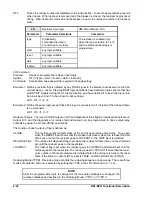
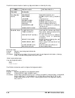
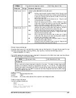
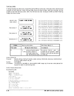
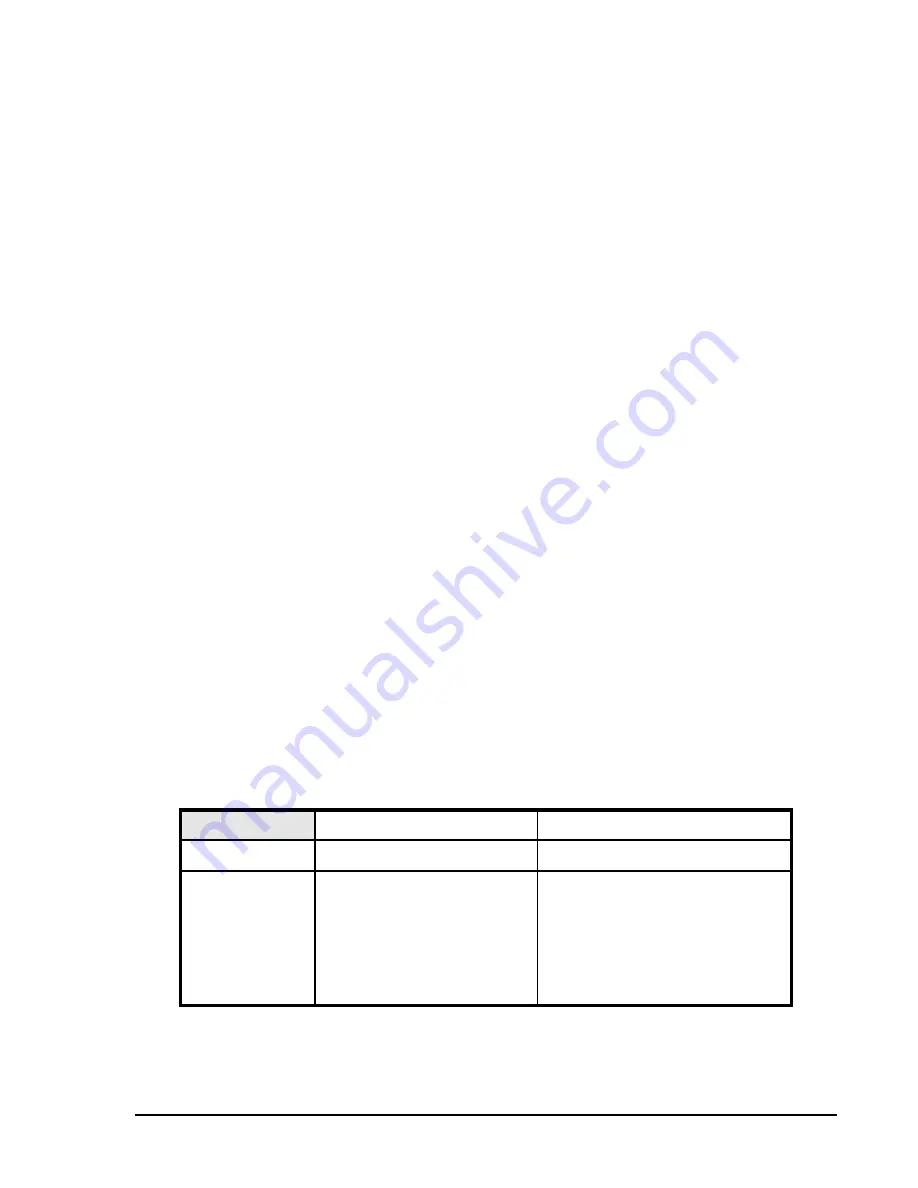
PHOLD
Output hold timers
HMI Menu Branch: N/A
Parameter
Parameter Selections
Comments
#####
0
(no minimum hold
time)
1
(200 millisecond.
minimum hold time)
Each digit of the PHOLD parameter
represents an output. The leftmost
digit represents OUT1. The right-
most digit represents OUT5.
Typically, the 200 millisecond hold
time will be enabled for all outputs
except those used for reclosing.
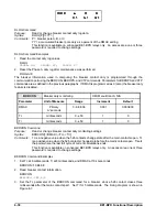
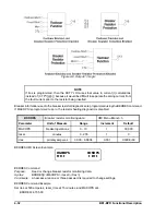
PHOLD Command
Purpose:
Read or program the output hold timer mask.
Syntax:
PHOLD[=<#####>]
Comments:
Access area password one, two, or three required to change settings. Default setting is
11111.
Summary of Contents for BE1-BPR
Page 31: ...BE1 BPR Application 2 17...
Page 42: ...3 4 BE1 BPR Human Machine Interface Figure 3 4 BE1 BPR Relay Vertical Mount Front View...
Page 43: ...BE1 BPR Human Machine Interface 3 5 Figure 3 5 BE1 BPR Relay Vertical Mount Rear View...
Page 49: ...4 6 BE1 BPR Functional Description Figure 4 2 Enhanced BE1 BPR Menu Display Screens...
Page 50: ...BE1 BPR Functional Description 4 7 Figure 4 3 Standard BE1 BPR Menu Display Screens...
Page 94: ...5 4 BE1 BPR BESTlogic Figure 5 1 BESTlogic Function Blocks...
Page 121: ...BE1 BPR Installation 7 3 Figure 7 3 Overall Dimensions Vertical Mount...
Page 122: ...7 4 BE1 BPR Installation Figure 7 4 Overall Dimensions Side View Vertical Mount...
Page 123: ...BE1 BPR Installation 7 5 Figure 7 5 Panel Drilling Diagram Vertical Mount...

